FAN-40HA-B Fan Module
Product Support
Table 1 lists the switch chassis matching a FAN-40HA-B fan module.
Appearance
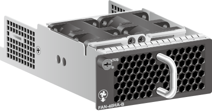
Figure 1 shows the appearance of a FAN-40HA-B fan module.
Function
A FAN-40HA-B fan module has two fans to cool the chassis. It is hot swappable.
Panel
Figure 2 shows the panel of a FAN-40HA-B fan module.
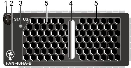
1. Captive screw |
2. Airflow flag (air out) |
3. Indicator |
4. Handle |
5. Two fans |
Table 2 describes the indicator on a FAN-40HA-B fan module panel.
Indicator |
Color |
Description |
|---|---|---|
STATUS: running status indicator |
Off |
The fan module is not running. |
Green |
Slow blinking: The fan module is working properly and communicating normally with the system. Fast blinking: The fan module is working properly but has not established communication with the system. |
|
Red |
Steady on: The fan module has a hardware fault and must be replaced. Blinking: An alarm has been generated and needs to be handled. Possible causes of the alarm include errors of dual in-line package (DIP) switches, short-circuit, fan blades blocked, and fault of the fan module. |
Specifications
Table 3 describes technical specifications of a FAN-40HA-B fan module.
Item |
Description |
|
|---|---|---|
| Dimensions (H x W x D) | 39.8 mm x 94.5 mm x 183.1 mm (1.57 in. x 3.72 in. x 7.21 in.) |
|
| Number of fans | Two counter-rotating fans with each containing two fan blades |
|
| Weight | 0.415 kg |
|
Maximum power consumption |
40 W |
|
Rated fan speed |
19000±10% revolutions per minute (RPM) |
|
Maximum airflow |
64 cubic feet per minute (CFM) |
|
| Part number | 02359097 |
|