RPS1800 Power Supply
Product Support
Table 1 lists the mapping between switch models and the RPS1800 power supply.
Power Module Name |
Product Support |
|---|---|
RPS1800 power supply |
S5700-LI, S5700S-LI, S5710-X-LI, S5720-X-LI, S5720-P-LI, S5720S-SI, S5720-X-EI, S5720-P-EI, S5720S-28X-LI-24S-AC, S5720-28X-SI-24S-AC, S5720-28X-SI-24S-DC, and S5700-26X-SI-12S-AC S6720-LI and S6720S-LI NOTE:
The S5720-16X-PWH-LI-AC, S5700-10P-PWR-LI-AC, and S5700-10P-LI-AC do not support the RPS. |
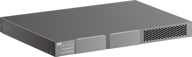
Appearance
Figure 1 shows the appearance of an RPS1800 power supply.
Function
The RPS1800 is a redundant power supply that ensures seamless failover if the internal power module of a switch fails. The RPS1800 can detect the failure of the internal power module on a connected switch and immediately supply power to this switch. The switch can continue operating without a restart.
- For non-PoE switches, the RPS1800 can provide 6:1 power redundancy without an 870 W PoE power module:
- The RPS1800 can connect to a maximum of six switches and ensure seamless failover for at most one switch if the internal power module of the switch fails.
- When the internal power module of the switch powered by the RPS1800 recovers, the RPS1800 immediately returns to the backup state.
- Among the six DC output ports, port 1 has the highest priority, and the other ports have the same priority. When the RPS1800 connects to six switches, the switch connected to port 1 preferentially receives power from the RPS1800.
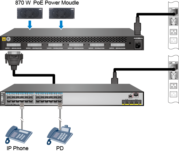
For S5700-LI and S5700S-LI PoE switches, the RPS1800 supports the forcible PoE power supply mode (default) and the 6:1 power cold redundancy mode.
Forcible PoE power supply mode:- The RPS1800 must be configured with one or two 870 W PoE power modules.
- The forcible PoE power supply mode is the default mode for the PoE switches connected to the RPS1800. In this mode, the RPS1800 provides PoE power supply to the PoE switches. When configured with one 870 W PoE power module, the RPS1800 can provide PoE power supply for only one PoE switch. When configured with two 870 W PoE power modules, the RPS1800 can provide PoE power supply for two PoE switches, 800 W PoE power for each switch.
- The PoE power provided by the RPS1800 and the PoE power of a switch's internal power modules do not accumulate. That is, when a PoE switch is connected to the RPS1800, its maximum PoE power is 800 W.
- When using 110 V power input, each 870 W PoE power module can provide only 400 W of PoE power. In this case, an RPS1800 must be configured with two 870 W PoE power modules if it is used to provide PoE power supply. Additionally, only one port of the RPS1800 can provide PoE power supply for a switch.
- The RPS1800 provides power redundancy for system and PoE power modules of the connected PoE switches. However, it can provide power redundancy for only two PoE switches at the same time.
- The six DC output ports have the same priority.
- You can use the rps cold-backup command to switch to the 6:1 power cold redundancy mode. The S5700-28P-PWR-LI-AC and S5700-52P-PWR-LI-AC do not support the 6:1 power cold redundancy mode.
6:1 power cold redundancy mode:- If the RPS1800 has no 870 W PoE power module, it provides the same functions for PoE switches as it does for non-PoE switches.
- If the RPS1800 has 870 W PoE power modules installed, it provides power redundancy for the system and PoE power modules of PoE switches but does not provide forcible PoE power supply for the switches.
- The RPS1800 can provide PoE power redundancy for only one switch at a time. It requires only one 870 W PoE power module when using 220 V power input and requires two 870 W PoE power module when using 110 V power input.
For S5720-LI PoE switches, the RPS1800 supports the 6:1 power cold redundancy mode.
6:1 power cold redundancy mode:- If the RPS1800 has no 870 W PoE power module, it provides the same functions for PoE switches as it does for non-PoE switches.
- If the RPS1800 has 870 W PoE power modules installed, it provides power redundancy for the system and PoE power modules of PoE switches but does not provide forcible PoE power supply for the switches.
- The RPS1800 can provide PoE power redundancy for only one switch at a time. It requires only one 870 W PoE power module when using 220 V power input and requires two 870 W PoE power module when using 110 V power input.

The 870 W PoE power modules and RPS cables are not hot swappable.
The RPS1800 only provides power redundancy for switches and cannot power on a switch directly.
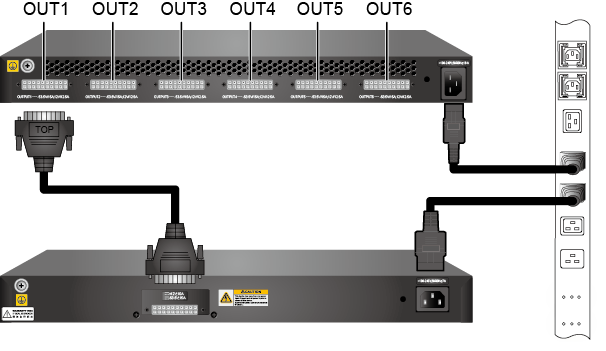
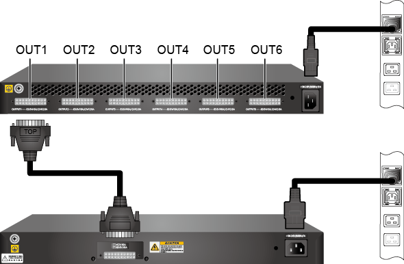
Application
The RPS1800 can be deployed on various networks to ensure non-stop operation of the networks. Figure 2 and Figure 3 show different deployments of the RPS1800.
When an RPS1800 uses the same external power supply system as the connected switches, it can prevent service interruption caused by failures of the switches' internal power modules. When an RPS1800 uses a different external power supply system than the connected switches, it can prevent service interruption caused by failures of switches' internal power modules and external power supply system. Therefore, this deployment is more reliable.
If one of switches connected to the RPS1800 encounters an internal power module failure, the RPS1800 provides seamless failover for the switch. Then the RPS1800 does not provide power backup for the other switches connected until the internal power module of the faulty switch is recovered or replaced.
If more than one connected switch has an internal power module failure, the RPS1800 preferentially provides power for the switch connected to port 1. If the switch connected to port 1 has an internal power module failure when the RPS1800 is providing power for a switch connected to another port, the RPS1800 immediately stops supplying power for this switch and starts providing power to the switch connected to port 1.
Panel Description
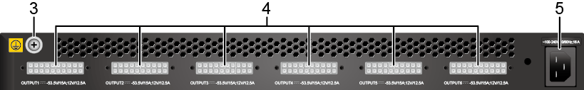
Figure 5 and Figure 6 show the appearance of an RPS1800 power supply.

1. RPS power indicators |
2. Two swappable power module slots NOTE:
870 W PoE power modules can be installed in the slots. |
3. Ground screw |
4. Six DC output ports NOTE:
The DC output ports connect to switches through RPS cables. |
5. AC power socket NOTE:
The AC power socket connects to an AC power source through an RPS1800 power cable. |
Table 2 describes the indicators on the panel of an RPS1800 power supply.
Indicator |
Color |
Description |
|---|---|---|
PWR |
Green |
Steady on: The power input is in normal range. |
- |
Off: The switch is powered off. |
|
TEMP |
Green |
Steady on: The temperature is in normal range. |
Red |
Steady on: The temperature is out of range. |
|
- |
Off: The switch is powered off. |
|
FAN |
Green |
Steady on: The fan module runs properly. |
- |
Off: The switch is powered off. |
|
OUTPUT |
Green |
Steady on: The RPS power supply is in cold backup state. Blinking: The RPS power supply is providing power. |
Orange |
Steady on: The RPS power supply is providing power for one or more switches and is therefore unavailable to supply power for more switches. |
|
- |
Off: The switch is powered off. |
Specifications
Table 3 describes technical specifications of an RPS1800 power supply.
Item |
Description (Without Power Modules Installed) |
Description (with One Power Module Installed) |
Description (with Two Power Modules Installed) |
|---|---|---|---|
Dimensions (H x W x D) |
43.6 mm x 442.0 mm x 310.0 mm (1.72 in. x 17.4 in. x 12.2 in.) |
||
Weight |
4.0 kg |
5.5 kg |
7.0 kg |
Operating temperature |
0°C to 50°C (at 0-2000 m altitude) |
||
Storage temperature |
-40°C to +70°C |
||
Relative humidity |
5% RH to 95% RH, noncondensing |
||
| Airflow direction | Air flows in through the DC output ports side and flows out through the power module side. | ||
Rated input voltage |
220/110 V AC, 50/60 Hz |
||
Input voltage range |
200 V AC to 240 V AC (220 V rated voltage input)/100 V AC to 120 V AC (110 V rated voltage input), 50/60 Hz |
||
Input current |
12 A |
||
Maximum output current |
12 V: 11.5 A |
|
|
Maximum output power |
12 V: 140 W |
|
|
| Part number | 02353857 | ||
Each interface of the RPS provides a maximum of 140 W power for the device and 800 W PoE power for PDs.