Overview of Local Attack Defense
Definition
Local attack defense protects the CPU of a device and prevents service interruption caused by attacks from a large number of valid packets or malicious packets.
Device CPUs need to process a large number of packets including valid packets and malicious attack packets on a network. The malicious attack packets overwhelm the CPUs, and thus affect services and cause a system breakdown. In addition, excess valid packets can also lead to high CPU usage, which degrades the CPU's performance and interrupts services.
To ensure that the CPU can process services in a timely manner, the device provides local attack defense functions. When a device is undergoing an attack, this function ensures uninterrupted service transmission and minimizes the impact on network services.
Functions Overview
The switch supports the following local attack defense functions to protect the CPU: CPU attack defense, attack source tracing, port attack defense, and user-level rate limiting. Table 1 describes these functions.
Function |
Definition |
|---|---|
The switch can limit the rate of all packets reaching the CPU, which means that only a specified number of packets can be sent to the CPU in a given period of time. This ensures that the CPU can properly process services. |
|
Attack source tracing protects the CPU against Denial of Service (DoS) attacks. This function enables the device to analyze packets sent to the CPU, collect statistics on the packets, and set a rate threshold for the packets. The device considers excess packets as attack packets, and finds the source user address or interface of the attack packets and generates logs or alarms to notify the network administrator. Accordingly, the network administrator can take measures to defend against the attacks, or the switch discards packets from the attack source. |
|
Port attack defense is an anti-DoS attack method. If a port receives a lot of protocol packets, the protocol packets occupy bandwidth. As a result, the protocol packets received by other ports cannot be sent to the CPU, and services are interrupted. The port attack defense function prevents attacks based on ports. |
|
User-level rate limiting identifies users based on MAC addresses, and rate-limits specified protocol packets, such as ARP, ND, and DHCP Request packets. If a single user initiates an attack, only traffic from this user is rate-limited and other users are not affected. |
CPU Attack Defense
CPCAR
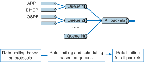
CPCAR rate-limits protocol packets sent to the control plane and schedules the packets to protect the control plane. CPCAR provides hierarchical device protection: rate limiting based on protocols, scheduling and rate limiting based on queues, and rate limiting for all packets, as shown in Figure 1.
- Rate limiting based on protocols: If the traffic volume of a protocol is too large, other protocol packets cannot be processed in a timely manner. The device uses CPCAR to limit the packet rate of each protocol. CPCAR includes the settings of Committed Information Rate (CIR) and Committed Burst Size (CBS) for each protocol. The device discards the protocol packets that exceed the corresponding rate limit. This ensures that protocols are independent of each other and all protocol packets can be processed.
- Scheduling and rate limiting based on queues: After rate limits for protocols are set, the device allocates a queue to each type of protocol. For example, the device allocates a queue to management protocols such as Telnet and SSH and a queue to routing protocols. Queues are scheduled based on weights or priorities. Services with the highest priority are processed first. You can also set a rate limit for packets in each queue sent to the CPU.
- Rate limiting for all packets: After rate limits are set for all packets sent to the CPU, the CPU can process more protocol packets without being overwhelmed.

- If all the rate limits in Figure 1 are set, the smallest rate limit takes effect.
- CPU attack defense functions cannot take effect on the packets that the management interface receives. If an attack occurs on the network connected to the management interface, you may fail to log in to or manage the device through the management interface. In this situation, it is recommended that you scan for viruses on all computers located on the connected network or optimize the networking to mitigate attacks.
- When multiple protocols are running, the protocol packets sent to the CPU may be discarded if they exceed the CIR or CBS, the maximum rate for sending packets from queues to the CPU, or the maximum number of packets that can be processed by CPU. If protocol packets are discarded, protocol flapping occurs.
The default CPCAR values for protocol packets cannot meet the dynamic requirements on the rate of protocol packets to be sent to the CPU. To resolve this problem, the switch can automatically adjust the CPCAR values of protocol packets based on the service volume, packet loss behavior, and CPU usage.
ALP
ALP refers to session-based application data protection, such as FTP, BGP, and OSPF sessions. This function prevents normal services from being affected when an attack occurs. When a session is set up, rate limiting based on protocols becomes ineffective. The device limits the session rate based on the rate set in ALP, ensuring reliability and stability of the session-related services.
Blacklist
CPU attack defense provides the blacklist function. A blacklist references an ACL. The device discards all packets that have the characteristics defined in the blacklist. You can add unauthorized users who are identified as attackers to the blacklist.
User-defined flows
CPU attack defense supports user-defined flows defined through ACLs. The switch limits the rate of packets matching the characteristics defined in user-defined flows sent to the CPU. The characteristics of attack flows can be flexibly defined in ACL rules, so you can configure user-defined flows for a network prone to unknown attacks.
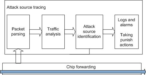
Attack Source Tracing
- The switch parses packets based on IP addresses, MAC addresses, and ports. The ports are identified by physical port numbers and VLAN IDs.
- The switch counts the number of received protocol packets to which attack source tracing is applied based on IP addresses, MAC addresses, or port numbers.
- When the rate of packets sent to the CPU exceeds the threshold in a given period of time, the switch considers that an attack has occurred.
- When detecting an attack, the switch reports a log and an alarm to the administrator, or takes punish actions, for example, discarding the packets.
Attack source tracing provides the whitelist function. After an ACL is configured to permit the packets from a port or a port is added to the whitelist, the device does not trace the source of the packets from this port. You can add authorized users or ports to the whitelist to ensure that packets from these users can be sent to the CPU.
Port Attack Defense
- Analyzes packets received by each port, and counts the protocol packets to which port attack defense is applied based on ports.
- Considers that an attack has occurred when the rate of packets sent to the CPU exceeds the rate threshold.
Records a log, and moves the packets within the protocol rate limit to a low-priority queue waiting for CPU processing or discards the excess packets. Note that the S5730-SI, S5730S-EI, S5720-SI, S5720I-SI, S5720S-SI, S6720S-SI, and S6720-SI cannot move the packets within the protocol rate limit to a low-priority queue, but retain the original queue to send the packets to the CPU for processing. For a description about protocol-based rate limiting and queue-based scheduling, see CPU Attack Defense.
The rate limiting actions taken by port attack defense have a minor impact compared to the punish actions taken by attack source tracing.
Port attack defense provides the whitelist function. After an ACL is configured to permit the packets from a port or a port is added to the whitelist, the switch does not trace the source of or limit the rate of the packets from this port. You can add authorized users or ports to the whitelist to ensure that packets from these users can be sent to the CPU.
User-Level Rate Limiting
- When receiving specified protocol packets, the switch performs a hash calculation on the source MAC addresses and places the packets into different buckets.
- When the number of packets that are placed in a bucket within 1 second exceeds the rate limit, the bucket discards the packets. The switch counts the number of discarded packets every 10 minutes. When the number of discarded packets within 10 minutes exceeds 2000, the switch reports a packet discard log for this bucket. If the total numbers of discarded packets in many buckets exceed 2000, the switch records the packet discard logs for the top 10 buckets.