Interworking with an NLB Cluster
Network load balancing (NLB) is developed by Microsoft for clusters set up using multiple Windows servers. The interworking between devices and the NLB cluster is important for an enterprise using the Windows server operating system.
Overview of NLB Cluster
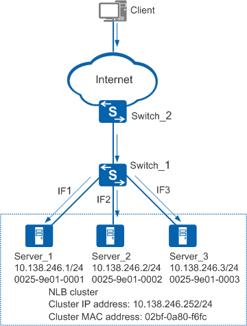
- Unicast mode: A unicast cluster MAC address starts with 02bf. When a device is connected to an NLB cluster in unicast mode, the device can learn only one outbound interface corresponding to the cluster IP address in the ARP entry. Therefore, only one NLB server can receive packets destined for the cluster IP address.
- Multicast mode: A multicast cluster MAC address starts with 03bf. When a device is connected to an NLB cluster in multicast mode, the device cannot learn the ARP entry with a multicast MAC address by default. After dynamic multicast MAC address learning is enabled or a static ARP entry is bound, the device can learn only one outbound interface. Therefore, only one NLB server can receive packets destined for the cluster IP address.
- IGMP multicast mode: An IGMP multicast cluster MAC address starts with 0100-5e. If the device connects to an NLB cluster working in IGMP multicast mode and an NLB server in the cluster can send IGMP packets, the device can learn the outbound interface of the server through the packets. Only the NLB server that sends IGMP packets can receive packets destined for the cluster IP address.
The device cannot send packets destined for the cluster IP address to all servers in the NLB cluster. This can be solved using the following methods.
Method for Interworking with the NLB Cluster
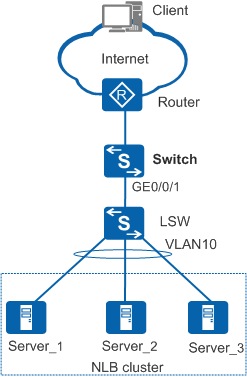
When NLB servers are directly connected to the Layer 2 switch (see Figure 2), the interworking is implemented directly in unicast mode. However, to implement the interworking in multicast mode, static ARP entries must be configured on the Layer 3 switch (Switch).
When NLB servers are directly connected to the Layer 3 switch, the device can be connected to the NLB cluster if the device supports multi-interface ARP. If the device does not support multi-interface ARP, add Layer 2 switches to enable the device to connect to the NLB cluster. If you do not have sufficient Layer 2 switches, use physical link loopback.
Multi-interface ARP
From V200R003C00, the device supports multi-interface ARP. Cluster IP addresses and cluster MAC addresses are bound in the static ARP table, and cluster MAC addresses and interface connecting to NLB servers are bound in the multi-interface MAC address table. In this way, the device sends packets destined for the cluster IP address from interfaces connecting to NLB servers so that all NLB servers can receive the packets.
Adding Layer 2 switches
Add a Layer 2 switch to connect the device to the NLB cluster if the existing device does not support multi-interface ARP. As shown in Figure 2, deploy a Layer 2 switch (LSW) between the Layer 3 switch (Switch) and the NLB cluster and configure the VLANIF interface mapping GE0/0/1 as the NLB cluster's gateway. After reaching LSW, the packet sent from the Switch to the cluster IP address is broadcast in VLAN 10, so all NLB servers can receive the packet.
By default, the device cannot learn an ARP entry with a multicast MAC address. Therefore, when NLB servers work in multicast mode, enable dynamic learning for multicast MAC addresses or configure a static ARP entry on the Switch. In the static ARP entry, the IP address is the cluster IP address, the MAC address is the cluster MAC address, and the outbound interface is GE0/0/1.
Physical link loopback
Physical link loopback allows the interworking between NLB servers in unicast or multicast mode and a stand-alone device, a VRRP group, or a stack when multi-interface ARP is not supported.
The interworking between a stand-alone device and NLB servers in unicast mode is used as an example. After packets destined for the NLB cluster reach the Switch, the Switch sends the packets to GE0/0/5 based on ARP entries. After the packets are sent to GE0/0/4 in untagged mode, other interfaces in VLAN 100 (including GE0/0/1 through GE0/0/3 connected to NLB servers) can copy the packets so that all NLB servers can receive the packets. The implementation of the interworking between NLB servers and a VRRP group or a stack is similar and therefore is not mentioned here.

The networking applied in multicast mode is similar to that in unicast mode. The only difference is that the device cannot learn ARP entries with multicast MAC addresses by default. To allow the device to learn such ARP entries, enable dynamic learning for multicast MAC addresses or configure a static ARP entry on the Switch. In the static ARP entry, the IP address is the cluster IP address, the MAC address is the cluster multicast MAC address, and the outbound interface is the interface corresponding to the cluster gateway VLAN.
Stand-alone device
Figure 3 Interworking for a stand-alone device and an NLB cluster in unicast mode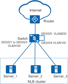
The configuration on Switch is as follows:
- Connect GE0/0/1 through GE0/0/3 to Server_1 through Server_3 respectively, and add the interfaces to VLAN 100.
- Disable STP, RSTP, VBST, and MSTP on GE0/0/4 and GE0/0/5, and add the interfaces to VLAN 100 and VLAN 200 respectively in access mode.
- Configure an IP address for VLANIF 200 as the NLB cluster's gateway.
VRRP group
Figure 4 Interworking for a VRRP group and an NLB cluster in unicast mode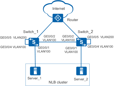
The configuration on the VRRP group is as follows:
- Connect the GE0/0/1 interfaces on Switch_1 and Switch_2 to Server_1 and Server_2 respectively, and add the interfaces to VLAN 100.
- Configure the link between the GE0/0/2 interfaces on Switch_1 and Switch_2 as the heartbeat link, and add the interfaces to VLAN 100.
- Disable STP, RSTP, VBST, and MSTP on GE0/0/4 and GE0/0/5 on Switch_1 and Switch_2, and add the interfaces to VLAN 100 and VLAN 200 respectively in access mode.
- Create a VRRP group on VLANIF 200 and configure the virtual IP address of the VRRP group for VLANIF 200 as the NLB cluster's gateway.
To reduce network workload, you are advised to separate the NLB cluster's gateway from other gateways.
In this networking, traffic from a switch to the NLB cluster passes along the heartbeat link to the peer switch and then passes along the self-loop line on the peer switch. In this case, if other servers use the same gateway as the NLB servers, other servers will receive traffic destined for the NLB cluster, causing an increase of network workload. For example, packets destined for the NLB cluster from Switch_1 pass along the heartbeat link to Switch_2. On Switch_2, packets are sent from GE0/0/4 to GE0/0/5. If VLANIF 200 on Switch_2 is also the gateway of non-NLB servers, packets are sent to non-NLB servers through GE0/0/5.
Stack
Figure 5 Interworking for a stack and an NLB cluster in unicast mode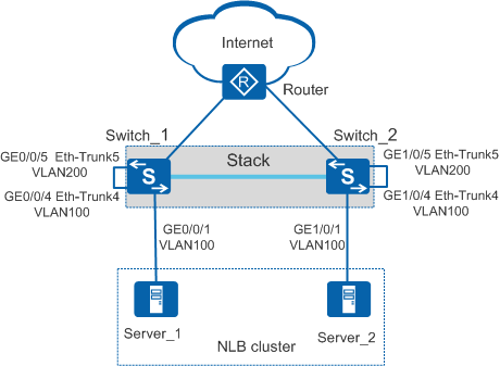
The configuration on the stack is as follows:
- Connect GE0/0/1 to Server_1, and GE1/0/1 to Server_2, and add the interfaces to VLAN 100.
- Add GE0/0/4 and GE1/0/4 to Eth-Trunk 4, and GE0/0/5 and GE1/0/5 to Eth-Trunk 5.
- Disable STP, RSTP, VBST, and MSTP on Eth-Trunk 4 and Eth-Trunk 5, and add Eth-Trunk 4 and Eth-Trunk 5 to VLAN 100 and VLAN 200 respectively in access mode.
- Configure an IP address for VLANIF 200 as the NLB cluster's gateway.