Example for Configuring Multi-Hop BFD
Networking Requirements
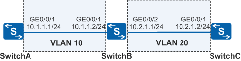
As shown in Figure 1, SwitchA is indirectly connected to SwitchC. Static routes are configured so that SwitchA can communicate with SwitchC. Faults on the link between SwitchA and SwitchC need to be fast detected.
Configuration Roadmap
The configuration roadmap is as follows:
Configure BFD sessions on SwitchA and SwitchC to detect the multi-hop route.
Procedure
- Configure devices to ensure network connectivity.
# Assign an IP address to each interface. SwitchA is used as an example. The configurations of SwitchB and SwitchC are similar to the configuration of SwitchA, and are not mentioned here.
<HUAWEI> system-view
[HUAWEI] sysname SwitchA
[SwitchA] vlan batch 10
[SwitchA] interface gigabitethernet 0/0/1
[SwitchA-GigabitEthernet0/0/1] port link-type hybrid
[SwitchA-GigabitEthernet0/0/1] port hybrid pvid vlan 10
[SwitchA-GigabitEthernet0/0/1] port hybrid untagged vlan 10
[SwitchA-GigabitEthernet0/0/1] quit
[SwitchA] interface vlanif 10
[SwitchA-Vlanif10] ip address 10.1.1.1 24
[SwitchA-Vlanif10] quit
- Configure a reachable static route between SwitchA and SwitchC.
The configuration of SwitchC is similar to the configuration of SwitchA, and is not mentioned here. For details, see the configuration files.
[SwitchA] ip route-static 10.2.1.0 24 10.1.1.2 - Configure multi-hop BFD.
# Create a BFD session between SwitchA and SwitchC.
[SwitchA] bfd
[SwitchA-bfd] quit
[SwitchA] bfd atoc bind peer-ip 10.2.1.2
[SwitchA-bfd-session-atoc] discriminator local 10
[SwitchA-bfd-session-atoc] discriminator remote 20
[SwitchA-bfd-session-atoc] commit
[SwitchA-bfd-session-atoc] quit
# Create a BFD session between SwitchC and SwitchA.
[SwitchC] bfd
[SwitchC-bfd] quit
[SwitchC] bfd ctoa bind peer-ip 10.1.1.1
[SwitchC-bfd-session-ctoa] discriminator local 20
[SwitchC-bfd-session-ctoa] discriminator remote 10
[SwitchC-bfd-session-ctoa] commit
[SwitchC-bfd-session-ctoa] quit
- Verify the configuration.
After the configuration, run the display bfd session all verbose command on SwitchA and SwitchC. You can see that a BFD session is set up and is in Up state. The command output on SwitchA is used as an example.
[SwitchA] display bfd session all verbose
--------------------------------------------------------------------------------
Session MIndex : 4097       (Multi Hop) State : Up      Name : atoc
--------------------------------------------------------------------------------
  Local Discriminator    : 10               Remote Discriminator   : 20
  Session Detect Mode    : Asynchronous Mode Without Echo Function
  BFD Bind Type          : Peer IP Address
  Bind Session Type      : Static
  Bind Peer IP Address   : 10.2.1.2
  Bind Interface         : -
  Track Interface        : -
  FSM Board Id           : 0                TOS-EXP                : 7
  Min Tx Interval (ms)   : 1000             Min Rx Interval (ms)   : 1000
  Actual Tx Interval (ms): 1000             Actual Rx Interval (ms): 1000
  Local Detect Multi     : 3                Detect Interval (ms)   : 3000
  Echo Passive           : Disable          Acl Number             : -
  Destination Port       : 3784             TTL                    : 254
  Proc Interface Status  : Disable          Process PST            : Disable
  WTR Interval (ms)      : -
  Active Multi           : 3                DSCP                   : -
  Last Local Diagnostic  : No Diagnostic
  Bind Application       : No Application Bind
  Session TX TmrID       : -                Session Detect TmrID   : -
  Session Init TmrID     : -                Session WTR TmrID      : -
  Session Echo Tx TmrID  : -
  PDT Index              : FSM-0 | RCV-0 | IF-0 | TOKEN-0
  Session Description    : -
--------------------------------------------------------------------------------

     Total UP/DOWN Session Number : 1/0
# Run the shutdown command on the GE0/0/1 interface of SwitchA to simulate a link fault.
[SwitchA] interface gigabitethernet 0/0/1
[SwitchA-GigabitEthernet0/0/1] shutdown
[SwitchA-GigabitEthernet0/0/1] quit
After the configuration, run the display bfd session all verbose command on SwitchA and SwitchB. You can see that a multi-hop BFD session is set up and the status is Down. The command output on SwitchA is used as an example.
[SwitchA] display bfd session all verbose
--------------------------------------------------------------------------------
Session MIndex : 4097       (Multi Hop) State : Down      Name : atoc
--------------------------------------------------------------------------------
  Local Discriminator    : 10               Remote Discriminator   : 20
  Session Detect Mode    : Asynchronous Mode Without Echo Function
  BFD Bind Type          : Peer IP Address
  Bind Session Type      : Static
  Bind Peer IP Address   : 10.2.1.2
  Bind Interface         : -
  Track Interface        : -
  FSM Board Id           : 0                TOS-EXP                : 7
  Min Tx Interval (ms)   : 1000             Min Rx Interval (ms)   : 1000
  Actual Tx Interval (ms): 13000            Actual Rx Interval (ms): 13000
  Local Detect Multi     : 3                Detect Interval (ms)   : -
  Echo Passive           : Disable          Acl Number             : -
  Destination Port       : 3784             TTL                    : 254
  Proc Interface Status  : Disable          Process PST            : Disable
  WTR Interval (ms)      : -
  Active Multi           : 3                DSCP                   : -
  Last Local Diagnostic  : Control Detection Time Expired
  Bind Application       : No Application Bind
  Session TX TmrID       : 16897            Session Detect TmrID   : -
  Session Init TmrID     : -                Session WTR TmrID      : -
  Session Echo Tx TmrID  : -
  PDT Index              : FSM-0 | RCV-0 | IF-0 | TOKEN-0
  Session Description    : -
--------------------------------------------------------------------------------

     Total UP/DOWN Session Number : 0/1
Configuration Files
SwitchA configuration file
#
sysname SwitchA
#
vlan batch 10
#
bfd
#
interface Vlanif10
 ip address 10.1.1.1 255.255.255.0
#
interface GigabitEthernet0/0/1
 port link-type hybrid
 port hybrid pvid vlan 10
 port hybrid untagged vlan 10
#
bfd atoc bind peer-ip 10.2.1.2
 discriminator local 10
 discriminator remote 20
 commit
#
ip route-static 10.2.1.0 255.255.255.0 10.1.1.2
#
return
SwitchB configuration file
#
sysname SwitchB
#
vlan batch 10 20
#
interface Vlanif10
 ip address 10.1.1.2 255.255.255.0
#
interface Vlanif20
 ip address 10.2.1.1 255.255.255.0
#
interface GigabitEthernet0/0/1
 port link-type hybrid
 port hybrid pvid vlan 10
 port hybrid untagged vlan 10
#
interface GigabitEthernet0/0/2
 port link-type hybrid
 port hybrid pvid vlan 20
 port hybrid untagged vlan 20
#
return
SwitchC configuration file
#
sysname SwitchC
#
vlan batch 20
#
bfd
#
interface Vlanif20
 ip address 10.2.1.2 255.255.255.0
#
interface GigabitEthernet0/0/1
 port link-type hybrid
 port hybrid pvid vlan 20
 port hybrid untagged vlan 20
#
bfd ctoa bind peer-ip 10.1.1.1
 discriminator local 20
 discriminator remote 10
 commit
#
ip route-static 10.1.1.0 255.255.255.0 10.2.1.1
#
return