Example for Configuring Association Between a BFD Session and an Interface
Networking Requirements
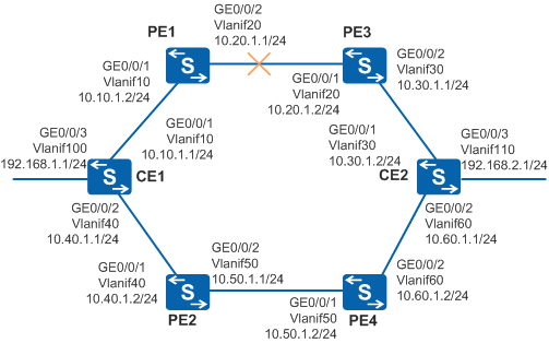
As shown in Figure 1, CE1 is dual-homed to PE1 and PE2, and CE2 is dual-homed to PE3 and PE4. Traffic is forwarded through the primary path CE1 -> PE1 -> PE3 -> CE2. It is required that faults on links between PEs be fast detected so that CEs can detect faults and traffic is switched to the standby path CE1 -> PE2 -> PE4 -> CE2.

The CEs must be directly connected to the PEs and no Layer 2 devices are deployed between CE1 and PE1 and between CE2 and PE2.
In this scenario, to avoid loops, ensure that all connected interfaces have STP disabled and connected interfaces are removed from VLAN 1. If STP is enabled and VLANIF interfaces of switches are used to construct a Layer 3 ring network, an interface on the network will be blocked. As a result, Layer 3 services on the network cannot run normally.
Configuration Roadmap
The configuration roadmap is as follows:
Configure devices to advertise routes through OSPF and set the OSPF cost of VLANIF 40 on CE1 and VLANIF 60 on CE2 to 10 so that traffic is transmitted through the primary path CE1 -> PE1 -> PE3 -> CE2.
Create a BFD session on PE1 to detect the directly connected link between PE1 and PE3.
Create a BFD session on PE3 to detect the directly connected link between PE3 and PE1.
Associate the BFD session with GE0/0/1 on PE1, and associate the BFD session with GE0/0/2 on PE3.
Procedure
- Configure devices to ensure network connectivity.
# Assign an IP address to each interface. PE1 is used as an example. The configurations of PE2, PE3, PE4, CE1 and CE2are similar to the configuration of PE1, and are not mentioned here.
<HUAWEI> system-view
[HUAWEI] sysname PE1
[PE1] vlan batch 10 20
[PE1] interface gigabitethernet 0/0/1
[PE1-GigabitEthernet0/0/1] port link-type hybrid
[PE1-GigabitEthernet0/0/1] port hybrid pvid vlan 10
[PE1-GigabitEthernet0/0/1] port hybrid untagged vlan 10
[PE1-GigabitEthernet0/0/1] quit
[PE1] interface gigabitethernet 0/0/2
[PE1-GigabitEthernet0/0/2] port link-type hybrid
[PE1-GigabitEthernet0/0/2] port hybrid pvid vlan 20
[PE1-GigabitEthernet0/0/2] port hybrid untagged vlan 20
[PE1-GigabitEthernet0/0/2] quit
[PE1] interface vlanif 10
[PE1-Vlanif10] ip address 10.10.1.2 24
[PE1-Vlanif10] quit
[PE1] interface vlanif 20
[PE1-Vlanif20] ip address 10.20.1.1 24
[PE1-Vlanif20] quit
- Configure a routing protocol.
OSPF is used in this example.
Run OSPF on CEs and PEs. To ensure that traffic is transmitted through the path CE1 -> PE1 -> PE3 -> CE2, increase the OSPF cost of VLANIF 40 on CE1 and VLANIF 60 on CE2. For example, change the cost to 10.
The configurations of PE2, PE3, and PE4 are similar to the configuration of PE1, and are not mentioned here. For details, see the configuration files.
[PE1] ospf 1
[PE1-ospf-1] area 0.0.0.0
[PE1-ospf-1-area-0.0.0.0] network 10.10.1.0 0.0.0.255
[PE1-ospf-1-area-0.0.0.0] network 10.20.1.0 0.0.0.255
[PE1-ospf-1-area-0.0.0.0] quit
[PE1-ospf-1] quit
# Configure CE1.
[CE1] ospf 1
[CE1-ospf-1] area 0.0.0.0
[CE1-ospf-1-area-0.0.0.0] network 10.10.1.0 0.0.0.255
[CE1-ospf-1-area-0.0.0.0] network 10.40.1.0 0.0.0.255
[CE1-ospf-1-area-0.0.0.0] network 192.168.1.0 0.0.0.255
[CE1-ospf-1-area-0.0.0.0] quit
[CE1-ospf-1] quit
[CE1] interface vlanif 40
[CE1-Vlanif40] ospf cost 10
[CE1-Vlanif40] quit
# Configure CE2.
[CE2] ospf 1
[CE2-ospf-1] area 0.0.0.0
[CE2-ospf-1-area-0.0.0.0] network 10.30.1.0 0.0.0.255
[CE2-ospf-1-area-0.0.0.0] network 10.60.1.0 0.0.0.255
[CE2-ospf-1-area-0.0.0.0] network 192.168.2.0 0.0.0.255
[CE2-ospf-1-area-0.0.0.0] quit
[CE2-ospf-1] quit
[CE2] interface vlanif 60
[CE2-Vlanif60] ospf cost 10
[CE2-Vlanif60] quit
# Run the display ip routing-table command on CE1. You can see that the outbound interface for the route from CE1 to 192.168.2.0/24 is VLANIF 10, indicating that traffic is transmitted along the primary path.
[CE1] display ip routing-table Route Flags: R - relay, D - download to fib, T - to vpn-instance ------------------------------------------------------------------------------ Routing Tables: Public Destinations : 13 Routes : 13 Destination/Mask Proto Pre Cost Flags NextHop Interface 10.10.1.0/24 Direct 0 0 D 10.10.1.1 Vlanif10 10.10.1.1/32 Direct 0 0 D 127.0.0.1 Vlanif10 10.20.1.0/24 OSPF 10 2 D 10.10.1.2 Vlanif10 10.30.1.0/24 OSPF 10 3 D 10.10.1.2 Vlanif10 10.40.1.0/24 Direct 0 0 D 10.40.1.1 Vlanif40 10.40.1.1/32 Direct 0 0 D 127.0.0.1 Vlanif40 10.50.1.0/24 OSPF 10 11 D 10.40.1.2 Vlanif40 10.60.1.0/24 OSPF 10 12 D 10.40.1.2 Vlanif40 127.0.0.0/8 Direct 0 0 D 127.0.0.1 InLoopBack0 127.0.0.1/32 Direct 0 0 D 127.0.0.1 InLoopBack0 192.168.1.0/24 Direct 0 0 D 192.168.1.1 Vlanif100 192.168.1.1/32 Direct 0 0 D 127.0.0.1 Vlanif100 192.168.2.0/24 OSPF 10 4 D 10.10.1.2 Vlanif10 - Create BFD sessions.
# Configure PE1.
[PE1] bfd
[PE1-bfd] quit
[PE1] bfd pe1tope3 bind peer-ip 10.20.1.2 interface vlanif 20
[PE1-bfd-session-pe1tope3] discriminator local 1
[PE1-bfd-session-pe1tope3] discriminator remote 2
[PE1-bfd-session-pe1tope3] commit
[PE1-bfd-session-pe1tope3] quit
# Configure PE3.
[PE3] bfd
[PE3-bfd] quit
[PE3] bfd pe3tope1 bind peer-ip 10.20.1.1 interface vlanif 20
[PE3-bfd-session-pe3tope1] discriminator local 2
[PE3-bfd-session-pe3tope1] discriminator remote 1
[PE3-bfd-session-pe3tope1] commit
[PE3-bfd-session-pe3tope1] quit
- Associate BFD sessions with interfaces.
# Configure PE1.
[PE1] oam-mgr
[PE1-oam-mgr] oam-bind ingress bfd-session 1 trigger if-down egress interface gigabitethernet 0/0/1
[PE1-oam-mgr] quit
# Configure PE3.
[PE3] oam-mgr
[PE3-oam-mgr] oam-bind ingress bfd-session 2 trigger if-down egress interface gigabitethernet 0/0/2
[PE3-oam-mgr] quit
- Verify the configuration.
Run the shutdown command on GE0/0/1 of PE3 to simulate a link fault. After receiving the fault notification message encapsulated into a BFD packet sent by the OAM management module, CE1 can detect the link fault between PE1 and PE3.
[PE3] interface gigabitethernet 0/0/1
[PE3-GigabitEthernet0/0/1] shutdown
[PE3-GigabitEthernet0/0/1] quit
# Run the display bfd session all verbose command on PE1. You can see that the BFD session becomes Down and the value of Bind Application is ETHOAM.
[PE1] display bfd session all verbose
--------------------------------------------------------------------------------
Session MIndex : 258       (One Hop) State : Down        Name : pe1tope3
--------------------------------------------------------------------------------
  Local Discriminator    : 1                Remote Discriminator   : 2
  Session Detect Mode    : Asynchronous Mode Without Echo Function
  BFD Bind Type          : Interface(Vlanif20)
  Bind Session Type      : Static
  Bind Peer IP Address   : 10.20.1.2
  NextHop Ip Address     : 10.20.1.2
  Bind Interface         : Vlanif20
  FSM Board Id           : 0                TOS-EXP                : 7
  Min Tx Interval (ms)   : 1000             Min Rx Interval (ms)   : 1000
  Actual Tx Interval (ms): 11000            Actual Rx Interval (ms): 11000
  Local Detect Multi     : 3                Detect Interval (ms)   : -
  Echo Passive           : Disable          Acl Number             : -
  Destination Port       : 3784             TTL                    : 255
  Proc Interface Status  : Disable          Process PST            : Disable
  WTR Interval (ms)      : -
  Active Multi           : -                DSCP                   : -
  Last Local Diagnostic  : No Diagnostic
  Bind Application       : ETHOAM
  Session TX TmrID       : 16483            Session Detect TmrID   : -
  Session Init TmrID     : -                Session WTR TmrID      : -
  Session Echo Tx TmrID  : -
  PDT Index              : FSM-0 | RCV-0 | IF-0 | TOKEN-0
  Session Description    : -
--------------------------------------------------------------------------------

     Total UP/DOWN Session Number : 0/1
# Run the display ip routing table command on CE1 to check the route from CE1 to CE2. The next hop of 192.168.2.0/24 is 10.40.1.2. That is, the traffic is forwarded through the standby path.
[CE1] display ip routing-table
Route Flags: R - relay, D - download to fib, T - to vpn-instance
------------------------------------------------------------------------------
Routing Tables: Public
         Destinations : 9        Routes : 9

Destination/Mask    Proto   Pre  Cost      Flags NextHop         Interface

      10.40.1.0/24  Direct  0    0           D   10.40.1.1       Vlanif40
      10.40.1.1/32  Direct  0    0           D   127.0.0.1       Vlanif40
      10.50.1.0/24  OSPF    10   11          D   10.40.1.2       Vlanif40
      10.60.1.0/24  OSPF    10   12          D   10.40.1.2       Vlanif40
      127.0.0.0/8   Direct  0    0           D   127.0.0.1       InLoopBack0
      127.0.0.1/32  Direct  0    0           D   127.0.0.1       InLoopBack0
    192.168.1.0/24  Direct  0    0           D   192.168.1.1     Vlanif100
    192.168.1.1/32  Direct  0    0           D   127.0.0.1       Vlanif100
    192.168.2.0/24  OSPF    10   13          D   10.40.1.2       Vlanif40
Configuration Files
CE1 configuration file
#
sysname CE1
#
vlan batch 10 40 100
#
interface Vlanif10
 ip address 10.10.1.1 255.255.255.0
#
interface Vlanif40
 ip address 10.40.1.1 255.255.255.0
 ospf cost 10
#
interface Vlanif100
 ip address 192.168.1.1 255.255.255.0
#
interface GigabitEthernet0/0/1
 port link-type hybrid
 port hybrid pvid vlan 10
 port hybrid untagged vlan 10
#
interface GigabitEthernet0/0/2
 port link-type hybrid
 port hybrid pvid vlan 40
 port hybrid untagged vlan 40
#
interface GigabitEthernet0/0/3
 port link-type hybrid
 port hybrid pvid vlan 100
 port hybrid untagged vlan 100
#
ospf 1
 area 0.0.0.0
  network 10.10.1.0 0.0.0.255
  network 10.40.1.0 0.0.0.255
  network 192.168.1.0 0.0.0.255
#
return
CE2 configuration file
#
sysname CE2
#
vlan batch 30 60 110
#
interface Vlanif30
 ip address 10.30.1.2 255.255.255.0
#
interface Vlanif60
 ip address 10.60.1.1 255.255.255.0
 ospf cost 10
#
interface Vlanif110
 ip address 192.168.2.1 255.255.255.0
#
interface GigabitEthernet0/0/1
 port link-type hybrid
 port hybrid pvid vlan 30
 port hybrid untagged vlan 30
#
interface GigabitEthernet0/0/2
 port link-type hybrid
 port hybrid pvid vlan 60
 port hybrid untagged vlan 60
#
interface GigabitEthernet0/0/3
 port link-type hybrid
 port hybrid pvid vlan 110
 port hybrid untagged vlan 110
#
ospf 1
 area 0.0.0.0
  network 10.30.1.0 0.0.0.255
  network 10.60.1.0 0.0.0.255
  network 192.168.2.0 0.0.0.255
#
return
PE1 configuration file
#
sysname PE1
#
vlan batch 10 20
#
bfd
#
interface Vlanif10
 ip address 10.10.1.2 255.255.255.0
#
interface Vlanif20
 ip address 10.20.1.1 255.255.255.0
#
interface GigabitEthernet0/0/1
 port link-type hybrid
 port hybrid pvid vlan 10
 port hybrid untagged vlan 10
#
interface GigabitEthernet0/0/2
 port link-type hybrid
 port hybrid pvid vlan 20
 port hybrid untagged vlan 20
#
bfd pe1tope3 bind peer-ip 10.20.1.2 interface Vlanif20
 discriminator local 1
 discriminator remote 2
 commit
#
ospf 1
 area 0.0.0.0
  network 10.10.1.0 0.0.0.255
  network 10.20.1.0 0.0.0.255
#
oam-mgr
 oam-bind ingress bfd-session 1 trigger if-down egress interface GigabitEthernet0/0/1
#
return
PE2 configuration file
#
sysname PE2
#
vlan batch 40 50
#
interface Vlanif40
 ip address 10.40.1.2 255.255.255.0
#
interface Vlanif50
 ip address 10.50.1.1 255.255.255.0
#
interface GigabitEthernet0/0/1
 port link-type hybrid
 port hybrid pvid vlan 40
 port hybrid untagged vlan 40
#
interface GigabitEthernet0/0/2
 port link-type hybrid
 port hybrid pvid vlan 50
 port hybrid untagged vlan 50
#
ospf 1
 area 0.0.0.0
  network 10.40.1.0 0.0.0.255
  network 10.50.1.0 0.0.0.255
#
return
PE3 configuration file
#
sysname PE3
#
vlan batch 20 30
#
bfd
#
interface Vlanif20
 ip address 10.20.1.2 255.255.255.0
#
interface Vlanif30
 ip address 10.30.1.1 255.255.255.0
#
interface GigabitEthernet0/0/1
 port link-type hybrid
 port hybrid pvid vlan 20
 port hybrid untagged vlan 20
#
interface GigabitEthernet0/0/2
 port link-type hybrid
 port hybrid pvid vlan 30
 port hybrid untagged vlan 30
#
bfd pe3tope1 bind peer-ip 10.20.1.1 interface Vlanif20
 discriminator local 2
 discriminator remote 1
 commit
#
ospf 1
 area 0.0.0.0
  network 10.20.1.0 0.0.0.255
  network 10.30.1.0 0.0.0.255
#
oam-mgr
 oam-bind ingress bfd-session 2 trigger if-down egress interface GigabitEthernet0/0/2
#
return
PE4 configuration file
#
sysname PE4
#
vlan batch 50 60
#
interface Vlanif50
 ip address 10.50.1.2 255.255.255.0
#
interface Vlanif60
 ip address 10.60.1.2 255.255.255.0
#
interface GigabitEthernet0/0/1
 port link-type hybrid
 port hybrid pvid vlan 50
 port hybrid untagged vlan 50
#
interface GigabitEthernet0/0/2
 port link-type hybrid
 port hybrid pvid vlan 60
 port hybrid untagged vlan 60
#
ospf 1
 area 0.0.0.0
  network 10.50.1.0 0.0.0.255
  network 10.60.1.0 0.0.0.255
#
return