Example for Configuring Basic BGP Functions
Networking Requirements
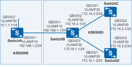
As shown in Figure 1, BGP runs between Switches; an EBGP connection is established between SwitchA and SwitchB; IBGP full-mesh connections are established between SwitchB, SwitchC, and SwitchD.

In this scenario, ensure that all connected interfaces have STP disabled. If STP is enabled and VLANIF interfaces of switches are used to construct a Layer 3 ring network, an interface on the network will be blocked. As a result, Layer 3 services on the network cannot run normally.
Configuration Roadmap
The configuration roadmap is as follows:
- Configure IBGP connections between SwitchB, SwitchC, and SwitchD.
- Configure an EBGP connection between SwitchA and SwitchB.
Procedure
- Create VLANs and add interfaces to the corresponding VLANs.
# Configure SwitchA. The configurations of SwitchB, SwitchC, and SwitchD are similar to the configuration of SwitchA.
<HUAWEI> system-view
[HUAWEI] sysname SwitchA
[SwitchA] vlan batch 10 50
[SwitchA] interface gigabitethernet 0/0/1
[SwitchA-GigabitEthernet0/0/1] port link-type trunk
[SwitchA-GigabitEthernet0/0/1] port trunk allow-pass vlan 10
[SwitchA-GigabitEthernet0/0/1] quit
[SwitchA] interface gigabitethernet 0/0/2
[SwitchA-GigabitEthernet0/0/2] port link-type trunk
[SwitchA-GigabitEthernet0/0/2] port trunk allow-pass vlan 50
[SwitchA-GigabitEthernet0/0/2] quit
- Assign an IP address to each VLANIF interface.
# Configure SwitchA. The configurations of SwitchB, SwitchC, and SwitchD are similar to the configuration of SwitchA.
[SwitchA] interface vlanif 10
[SwitchA-Vlanif10] ip address 192.168.1.2 24
[SwitchA-Vlanif10] quit
[SwitchA] interface vlanif 50
[SwitchA-Vlanif50] ip address 10.1.1.1 16
[SwitchA-Vlanif50] quit
- Configure IBGP connections.
# Configure SwitchB.
[SwitchB] bgp 65009
[SwitchB-bgp] router-id 172.17.2.2
[SwitchB-bgp] peer 172.16.1.2 as-number 65009
[SwitchB-bgp] peer 172.16.3.2 as-number 65009
[SwitchB-bgp] quit
# Configure SwitchC.
[SwitchC] bgp 65009
[SwitchC-bgp] router-id 172.17.3.3
[SwitchC-bgp] peer 172.16.3.1 as-number 65009
[SwitchC-bgp] peer 172.16.2.2 as-number 65009
[SwitchC-bgp] quit
# Configure SwitchD.
[SwitchD] bgp 65009
[SwitchD-bgp] router-id 172.17.4.4
[SwitchD-bgp] peer 172.16.1.1 as-number 65009
[SwitchD-bgp] peer 172.16.2.1 as-number 65009
[SwitchD-bgp] quit
- Configure EBGP connections.
# Configure SwitchA.
[SwitchA] bgp 65008
[SwitchA-bgp] router-id 172.17.1.1
[SwitchA-bgp] peer 192.168.1.1 as-number 65009
[SwitchA-bgp] quit
# Configure SwitchB.
[SwitchB] bgp 65009
[SwitchB-bgp] peer 192.168.1.2 as-number 65008
[SwitchB-bgp] quit
# Check the status of BGP connections.
[SwitchB] display bgp peer

 BGP local router ID : 172.17.2.2
 Local AS number : 65009
 Total number of peers : 3                 Peers in established state : 3

  Peer            V    AS  MsgRcvd  MsgSent  OutQ  Up/Down       State   PrefRcv

  172.16.1.2      4  65009     49       62     0   00:44:58   Established     0
  172.16.3.2      4  65009     56       56     0   00:40:54   Established     0
  192.168.1.2     4  65008     49       65     0   00:44:03   Established     0
You can view that the BGP connections between SwitchB and all the other Switches are set up.
- Configure SwitchA to advertise route 10.1.0.0/16.
# Configure SwitchA to advertise routes.
[SwitchA] bgp 65008
[SwitchA-bgp] ipv4-family unicast
[SwitchA-bgp-af-ipv4] network 10.1.0.0 255.255.0.0
[SwitchA-bgp-af-ipv4] quit
[SwitchA-bgp] quit
# Check the routing table of SwitchA.
[SwitchA] display bgp routing-table

 BGP Local router ID is 172.17.1.1
 Status codes: * - valid, > - best, d - damped,
               h - history,  i - internal, s - suppressed, S - Stale
               Origin : i - IGP, e - EGP, ? - incomplete


 Total Number of Routes: 1
      Network            NextHop        MED        LocPrf    PrefVal Path/Ogn

 *>   10.1.0.0/16           0.0.0.0         0                     0      i
# Check the routing table of SwitchB.
[SwitchB] display bgp routing-table

  BGP Local router ID is 172.17.2.2
 Status codes: * - valid, > - best, d - damped,
               h - history,  i - internal, s - suppressed, S - Stale
               Origin : i - IGP, e - EGP, ? - incomplete


 Total Number of Routes: 1
      Network            NextHop        MED        LocPrf    PrefVal Path/Ogn

 *>   10.1.0.0/16           192.168.1.2     0                     0      65008i
# Check the routing table of SwitchC.
[SwitchC] display bgp routing-table

 BGP Local router ID is 172.17.3.3
 Status codes: * - valid, > - best, d - damped,
               h - history,  i - internal, s - suppressed, S - Stale
               Origin : i - IGP, e - EGP, ? - incomplete


 Total Number of Routes: 1
     Network            NextHop        MED        LocPrf    PrefVal Path/Ogn

  i   10.1.0.0/16           192.168.1.2     0          100        0      65008i
According to the routing table, you can view that SwitchC has learned the route to the destination 10.1.0.0 in AS 65008, but the next hop 192.168.1.2 is unreachable. Therefore, this route is invalid.
- Configure BGP to import direct routes.
# Configure SwitchB.
[SwitchB] bgp 65009
[SwitchB-bgp] ipv4-family unicast
[SwitchB-bgp-af-ipv4] import-route direct
[SwitchB-bgp-af-ipv4] quit
[SwitchB-bgp] quit
# Check the BGP routing table of SwitchA.
[SwitchA] display bgp routing-table

  BGP Local router ID is 172.17.1.1
  Status codes: * - valid, > - best, d - damped,
               h - history,  i - internal, s - suppressed, S - Stale
               Origin : i - IGP, e - EGP, ? - incomplete


 Total Number of Routes: 4
    Network            NextHop        MED        LocPrf    PrefVal Path/Ogn

 *>   10.1.0.0/16           0.0.0.0         0                     0      i
 *>   172.16.1.0/24      192.168.1.1     0                     0      65009?
 *>   172.16.3.0/24      192.168.1.1     0                     0      65009?
      192.168.1.0        192.168.1.1     0                     0      65009?
# Check the routing table of SwitchC.
[SwitchC] display bgp routing-table

 BGP Local router ID is 172.17.3.3
 Status codes: * - valid, > - best, d - damped,
               h - history,  i - internal, s - suppressed, S - Stale
               Origin : i - IGP, e - EGP, ? - incomplete


 Total Number of Routes: 4
     Network            NextHop        MED        LocPrf    PrefVal Path/Ogn

 *>i  10.1.0.0/16           192.168.1.2     0          100        0      65008i
 *>i  172.16.1.0/24      172.16.3.1      0          100        0      ?
   i  172.16.3.0/24      172.16.3.1      0          100        0      ?
 *>i  192.168.1.0        172.16.3.1      0          100        0      ?
You can view that the route destined for 10.1.0.0 becomes valid, and the next hop is the address of SwitchA.
# Perform the ping operation to verify the configuration.
[SwitchC] ping 10.1.1.1
  PING 10.1.1.1: 56  data bytes, press CTRL_C to break
    Reply from 10.1.1.1: bytes=56 Sequence=1 ttl=255 time=31 ms
    Reply from 10.1.1.1: bytes=56 Sequence=2 ttl=255 time=47 ms
    Reply from 10.1.1.1: bytes=56 Sequence=3 ttl=255 time=31 ms
    Reply from 10.1.1.1: bytes=56 Sequence=4 ttl=255 time=16 ms
    Reply from 10.1.1.1: bytes=56 Sequence=5 ttl=255 time=31 ms

  --- 10.1.1.1 ping statistics ---
    5 packet(s) transmitted
    5 packet(s) received
    0.00% packet loss
    round-trip min/avg/max = 16/31/47 ms
Configuration Files
SwitchA configuration file
#
sysname SwitchA
#
vlan batch 10 50
#
interface Vlanif10
 ip address 192.168.1.2 255.255.255.0
#
interface Vlanif50
 ip address 10.1.1.1 255.255.0.0
#
interface GigabitEthernet0/0/1
 port link-type trunk
 port trunk allow-pass vlan 10
#
interface GigabitEthernet0/0/2
 port link-type trunk
 port trunk allow-pass vlan 50
#
bgp 65008
 router-id 172.17.1.1
 peer 192.168.1.1 as-number 65009
 #
 ipv4-family unicast
  undo synchronization
  network 10.1.0.0 255.255.0.0
  peer 192.168.1.1 enable
#
return
SwitchB configuration file
#
sysname SwitchB
#
vlan batch 10 20 30
#
interface Vlanif10
 ip address 192.168.1.1 255.255.255.0
#
interface Vlanif20
 ip address 172.16.3.1 255.255.255.0
#
interface Vlanif30
 ip address 172.16.1.1 255.255.255.0
#
interface GigabitEthernet0/0/1
 port link-type trunk
 port trunk allow-pass vlan 10
#
interface GigabitEthernet0/0/2
 port link-type trunk
 port trunk allow-pass vlan 20
#
interface GigabitEthernet0/0/3
 port link-type trunk
 port trunk allow-pass vlan 30
#
bgp 65009
 router-id 172.17.2.2
 peer 172.16.1.2 as-number 65009
 peer 172.16.3.2 as-number 65009
 peer 192.168.1.2 as-number 65008
 #
 ipv4-family unicast
  undo synchronization
  import-route direct
  peer 172.16.1.2 enable
  peer 172.16.3.2 enable
  peer 192.168.1.2 enable
#
return
SwitchC configuration file
#
sysname SwitchC
#
vlan batch 20 40
#
interface Vlanif20
 ip address 172.16.3.2 255.255.255.0
#
interface Vlanif40
 ip address 172.16.2.1 255.255.255.0
#
interface GigabitEthernet0/0/1
 port link-type trunk
 port trunk allow-pass vlan 20
#
interface GigabitEthernet0/0/2
 port link-type trunk
 port trunk allow-pass vlan 40
#
bgp 65009
 router-id 172.17.3.3
 peer 172.16.2.2 as-number 65009
 peer 172.16.3.1 as-number 65009
 #
 ipv4-family unicast
  undo synchronization
  peer 172.16.2.2 enable
  peer 172.16.3.1 enable
#
return
SwitchD configuration file
#
sysname SwitchD
#
vlan batch 30 40
#
interface Vlanif30
 ip address 172.16.1.2 255.255.255.0
#
interface Vlanif40
 ip address 172.16.2.2 255.255.255.0
#
interface GigabitEthernet0/0/1
 port link-type trunk
 port trunk allow-pass vlan 30
#
interface GigabitEthernet0/0/2
 port link-type trunk
 port trunk allow-pass vlan 40
#
bgp 65009
 router-id 172.17.4.4
 peer 172.16.1.1 as-number 65009
 peer 172.16.2.1 as-number 65009
 #
 ipv4-family unicast
  undo synchronization
  peer 172.16.1.1 enable
  peer 172.16.2.1 enable
#
return