Example for Configuring Association Between CFM and EFM
Networking Requirements
As networks develop quickly, more and more IP networks are used to carry multiple services such as voice and video services. These services pose high requirements on network reliability and rapid fault detection.
Link detection protocols are usually deployed on a network to detect link connectivity and faults. A single fault detection protocol cannot detect all faults in all links on a complex network. Network environments and user requirements need to be analyzed, and various detection techniques are required to implement rapid link fault detection.
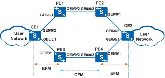
Connectivity of links between CE1 and PE3, between PE3 and PE4, and between PE4 and CE2 can be detected.
When the link between CE1 and PE3 becomes faulty, CE2 can detect the fault, preventing return traffic from being forwarded to PE4.
When the link between PE3 and PE4 becomes faulty, CE1 or CE2 can detect the fault.
When the link between CE1 and PE3 goes faulty, a active/standby link switchover can be implemented.
Configuration Roadmap
Configure EFM for links between CE1 and PE3 and between CE2 and PE4 to monitor link connectivity.
Configure CFM for the link between PE3 and PE4 to monitor link connectivity.
Configure association between EFM and interfaces on CE2. When EFM detects a link fault between CE1 and PE3, traffic can be switched to the backup link and return traffic is not forwarded to PE4.
Configure association between CFM and EFM on PE3 and PE4 so that CFM and EFM can notify each other of faults.
Procedure
- Configure basic EFM functions.
# Enable EFM on CE1 globally.
<HUAWEI> system-view
[HUAWEI] sysname CE1
[CE1] efm enable
# Enable EFM on CE2 globally.
<HUAWEI> system-view
[HUAWEI] sysname CE2
[CE2] efm enable
# Enable EFM on PE3 globally.
<HUAWEI> system-view
[HUAWEI] sysname PE3
[PE3] efm enable
# Enable EFM on PE4 globally.
<HUAWEI> system-view
[HUAWEI] sysname PE4
[PE4] efm enable
# Enable EFM on GE0/0/1 of CE1.
[CE1] interface gigabitethernet 0/0/1
[CE1-GigabitEthernet0/0/1] efm enable
[CE1-GigabitEthernet0/0/1] quit
# Enable EFM on GE0/0/1 of CE2.
[CE2] interface gigabitethernet 0/0/1
[CE2-GigabitEthernet0/0/1] efm enable
[CE2-GigabitEthernet0/0/1] quit
# Enable EFM on GE0/0/1 of PE3.
[PE3] interface gigabitethernet 0/0/1
[PE3-GigabitEthernet0/0/1] efm enable
[PE3-GigabitEthernet0/0/1] quit
# Enable EFM on GE0/0/1 of PE4.
[PE4] interface gigabitethernet 0/0/1
[PE4-GigabitEthernet0/0/1] efm enable
[PE4-GigabitEthernet0/0/1] quit
# Verify the configuration.
If EFM is correctly configured on PE3, CE1, PE4, and CE2, GE0/0/1 of these devices will enter the handshake stage. Run the display efm session { all | interface interface-type interface-num } command on one of these devices. The command output shows that the EFM status on GE0/0/1 is detect.
[CE1] display efm session all
  Interface                 EFM State                   Loopback Timeout
  ----------------------------------------------------------------------
  GigabitEthernet0/0/1     detect                        --
- Configure basic CFM functions.
An outward-facing MEP in a VLAN is used as an example to describe how to configure basic CFM functions.
# Configure basic CFM functions on PE3.
[PE3] vlan 2
[PE3-vlan2] quit
[PE3] interface gigabitethernet 0/0/2
[PE3-GigabitEthernet0/0/2] port link-type trunk
[PE3-GigabitEthernet0/0/2] port trunk allow-pass vlan 2
[PE3-GigabitEthernet0/0/2] quit
[PE3] cfm version standard
[PE3] cfm enable
[PE3] cfm md md1
[PE3-md-md1] ma ma1
[PE3-md-md1-ma-ma1] map vlan 2
[PE3-md-md1-ma-ma1] mep mep-id 1 interface gigabitethernet 0/0/2 outward
[PE3-md-md1-ma-ma1] remote-mep mep-id 2
[PE3-md-md1-ma-ma1] mep ccm-send enable
[PE3-md-md1-ma-ma1] remote-mep ccm-receive enable
[PE3-md-md1-ma-ma1] quit
[PE3-md-md1] quit
# Configure basic CFM functions on PE4.
[PE4] vlan 2
[PE4-vlan2] quit
[PE4] interface gigabitethernet 0/0/2
[PE4-GigabitEthernet0/0/2] port link-type trunk
[PE4-GigabitEthernet0/0/2] port trunk allow-pass vlan 2
[PE4-GigabitEthernet0/0/2] quit
[PE4] cfm version standard
[PE4] cfm enable
[PE4] cfm md md1
[PE4-md-md1] ma ma1
[PE4-md-md1-ma-ma1] map vlan 2
[PE4-md-md1-ma-ma1] mep mep-id 2 interface gigabitethernet 0/0/2 outward
[PE4-md-md1-ma-ma1] remote-mep mep-id 1
[PE4-md-md1-ma-ma1] mep ccm-send enable
[PE4-md-md1-ma-ma1] remote-mep ccm-receive enable
[PE4-md-md1-ma-ma1] quit
[PE4-md-md1] quit
# Verify the configuration.
Run the display cfm remote-mep command on PE3 or PE4. If the value of the CFM Status field is up, the CFM configuration is correct.
[PE3] display cfm remote-mep The total number of RMEPs is : 1 The status of RMEPs : 1 up, 0 down, 0 disable -------------------------------------------------- MD Name : md1 Level : 0 MA Name : ma1 RMEP ID : 2 VLAN ID : 2 VSI Name : -- L2VC ID : -- MAC : 0044-0141-5411 CCM Receive : enabled Trigger-If-Down : disabled CFM Status : up Alarm Status : none Interface TLV : -- Connect Status : up - Configure association between EFM and CFM.
# Configure association between EFM and CFM on PE3.
[PE3] oam-mgr
[PE3-oam-mgr] oam-bind cfm md md1 ma ma1 efm interface gigabitethernet 0/0/1
[PE3-oam-mgr] quit
# Configure association between EFM and CFM on PE4.
[PE4] oam-mgr
[PE4-oam-mgr] oam-bind cfm md md1 ma ma1 efm interface gigabitethernet 0/0/1
[PE4-oam-mgr] quit
- Configure association between EFM and an interface on CE2.
[CE2] interface gigabitethernet 0/0/1
[CE2-GigabitEthernet0/0/1] efm trigger if-down
[CE2-GigabitEthernet0/0/1] quit
- Verify the configuration.
# After association functions are configured, run the shutdown command on GE0/0/1 of CE1 to simulate a fault on the link between CE1 and PE3.
[CE1] interface gigabitethernet 0/0/1
[CE1-GigabitEthernet0/0/1] shutdown
[CE1-GigabitEthernet0/0/1] quit
# Run the display interface interface-type interface-num command on GE0/0/1 of CE2. The command output shows that the Line protocol current state field value is DOWN (EFM down), indicating that the fault is transmitted from the link between CE1 and PE3 to the link between PE4 and CE2.
[CE2] display interface gigabitethernet 0/0/1
GigabitEthernet0/0/1 current state : UP
Line protocol current state : DOWN (EFM down)
...

The output of the display interface gigabitethernet 0/0/1 command displays information that you need to concern and "..." indicates that information is omitted.
Configuration Files
CE1 configuration file
#
sysname CE1
#
efm enable
#
interface GigabitEthernet0/0/1
 efm enable
#
return
PE3 configuration file
#
sysname PE3
#
vlan batch 2
#
cfm enable
#
efm enable
#
interface GigabitEthernet0/0/1
 efm enable
#
interface GigabitEthernet0/0/2
 port link-type trunk
 port trunk allow-pass vlan 2
#
cfm md md1
 ma ma1
  map vlan 2
  mep mep-id 1 interface GigabitEthernet0/0/2 outward
  mep ccm-send mep-id 1 enable
  remote-mep mep-id 2
  remote-mep ccm-receive mep-id 2 enable
#
oam-mgr
 oam-bind ingress cfm md md1 ma ma1 egress efm interface GigabitEthernet0/0/1
 oam-bind ingress efm interface GigabitEthernet0/0/1 egress cfm md md1 ma ma1
#
return
PE4 configuration file
#
sysname PE4
#
vlan batch 2
#
cfm enable
#
efm enable
#
interface GigabitEthernet0/0/1
 efm enable
#
interface GigabitEthernet0/0/2
 port link-type trunk
 port trunk allow-pass vlan 2
#
cfm md md1
 ma ma1
  map vlan 2
  mep mep-id 2 interface GigabitEthernet0/0/2 outward
  mep ccm-send mep-id 2 enable
  remote-mep mep-id 1
  remote-mep ccm-receive mep-id 1 enable
#
oam-mgr
 oam-bind ingress cfm md md1 ma ma1 egress efm interface GigabitEthernet0/0/1
 oam-bind ingress efm interface GigabitEthernet0/0/1 egress cfm md md1 ma ma1
#
return
CE2 configuration file
#
sysname CE2
#
efm enable
#
interface GigabitEthernet0/0/1
 efm enable
 efm trigger if-down
#
return