Example for Configuring Deception
Networking Requirements
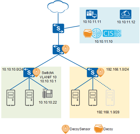
On the network shown in Figure 1:
- A DecoySensor protects IP addresses on the 192.168.1.0/24 network segment from being scanned.
- The DecoySensor protects TCP ports of devices on the 10.10.10.0/24 network segment from being scanned.
- If a hacker scans the 192.168.1.0/28 network segment, traffic sent by the hacker is immediately lured to the Decoy.
- The NMS device with IP address 10.10.11.11 periodically scans whether devices on the entire network are online. Therefore, its IP address needs to be added to the source IP address whitelist.
- The traditional device with IP address 10.10.10.22 does not respond to IP address scanning or TCP port scanning. Therefore, its IP address needs to be added to the destination IP address whitelist.
Deployment Guidelines
- You are advised to deploy DecoySensors on access switches.
- There must be reachable routes between switches and the Decoy.
- If a firewall is deployed between switches and the Decoy, you need to enable UDP ports 11514 and 10514 on the firewall.
- The following configurations must be performed on the switch. Otherwise, the deception function does not take effect.
- VLANIF interfaces are configured to send ARP packets destined for other devices to the CPU using the undo arp optimized-passby enable command.
- The optimized ARP reply function is disabled using the arp optimized-reply disable command.
- At least one of the detection network segment and the bait network segment must be configured.
- The switch can only detect scanning of IP addresses on the same network segment as the primary IP address of the VLANIF interface.
- A switch cannot use the virtual IP address of a VRRP group or the IP address of the management network interface to connect to a Decoy.
- A bait network segment cannot contain the device management address and any network segment (0.0.0.0). Otherwise, the devices cannot be managed remotely.
- To enable the Agile Controller-Campus to deliver associated policies to switches, configure the free mobility function on the switches and ensure that the switches can communicate with the Agile Controller-Campus.
- You can add the IP addresses of devices that proactively detect the network (such as the NMS) to the source IP address whitelist to prevent them from being incorrectly considered to be attackers by DecoySensors.
- You can add the IP addresses of devices that do not respond to ARP requests and port connection requests (such as traditional printers) to the destination IP address whitelist to prevent normal traffic sent to these devices from being lured.
Procedure
- Deploy DecoySensors on Switches. The following uses SwitchA
as an example. The configuration on other switches is similar to that
on SwitchA, and is not mentioned here.
- Configure the Decoy in the CIS.
- Configure the deception service.
- Log in to the CIS using an administrator account.
- Choose , and click Deception to expand the list of deception service instances.
Click
 in the Operation column of the Decoy
host. The Deception CisServer page is displayed.
On the Basic configuration tab page, set parameters
and click Save.
in the Operation column of the Decoy
host. The Deception CisServer page is displayed.
On the Basic configuration tab page, set parameters
and click Save.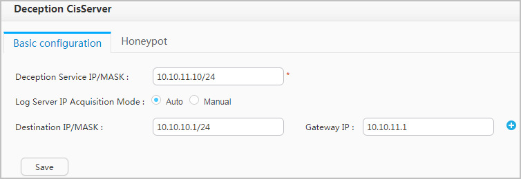
Parameter Description Deception Service IP/MASK IP address and subnet mask of the Decoy. Log Server IP Acquisition Mode The Auto mode is recommended, because deception information is transmitted to the collector through an internal interface more quickly in this mode. If you select the Manual mode, enter the IP address of the collector. Destination IP/MASK IP address and subnet mask of the DecoySensor. NOTE:The Destination IP/MASK and Gateway IP parameters need to be set only when IP addresses of the DecoySensor and Decoy are on different network segments.
Gateway IP Gateway IP address used by the Decoy to access the DecoySensor.
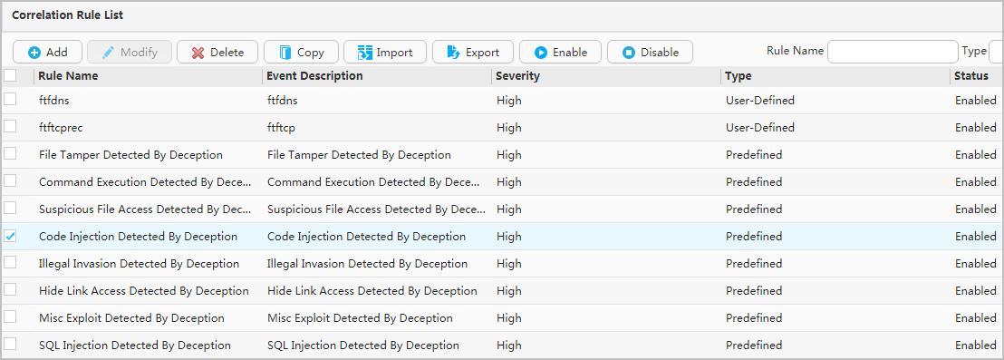
- Enable the corresponding deception rule.
# Return to the CIS homepage, choose , select the target rule, and click Enable. You can enable an existing rule or create and enable a new rule.
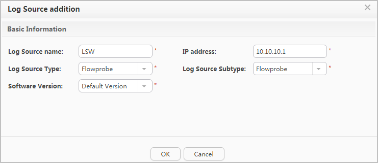
- Configure the log source.
- Choose .
Click Log Source addition, configure the DecoySensor as the log source, and click OK. In the dialog box that is displayed, click OK.
- Choose .
- Click Collector to view the running status of the host where the collector service resides.
- Click in the Operation column of the Decoy host.
The collector configuration page is displayed.
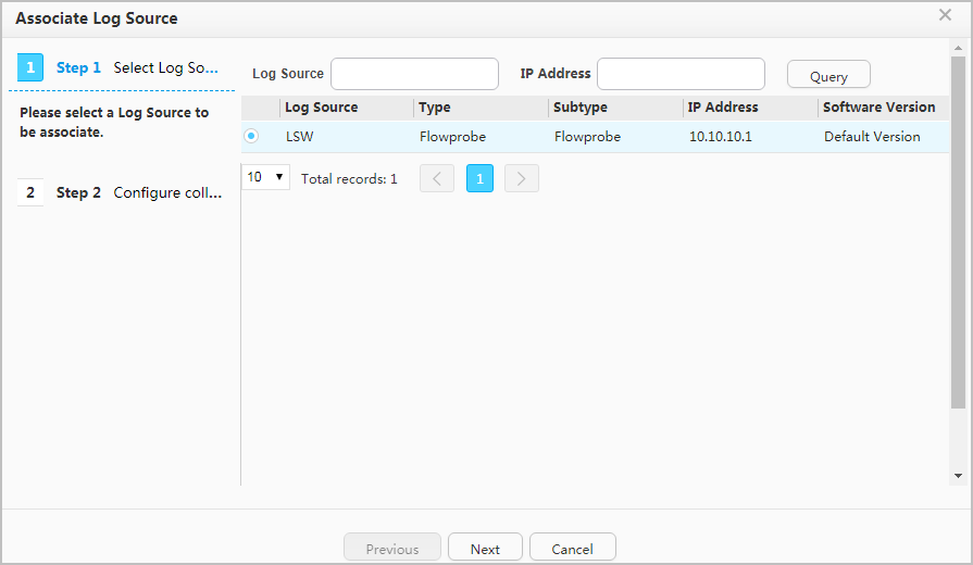
Click Add, select the log source to be associated, and click Next.
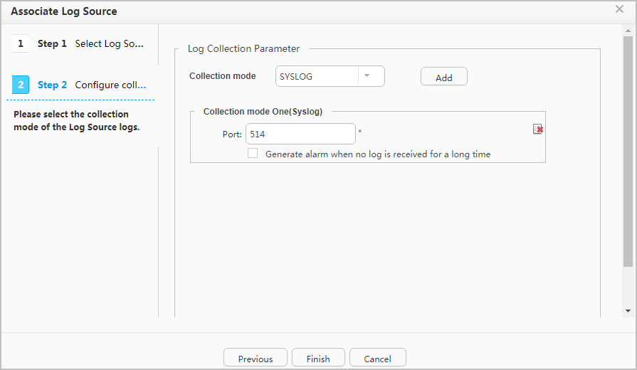
Set the log collection mode to SYSLOG for the log source, click Add, and then click Finish.
- Configure the deception service.
- Configure parameters used by the CIS to deliver associated
policies to the Agile Controller-Campus.
- Configure the Agile Controller-Campus.
- Log in to the Agile Controller-Campus using an administrator account.
- Choose .
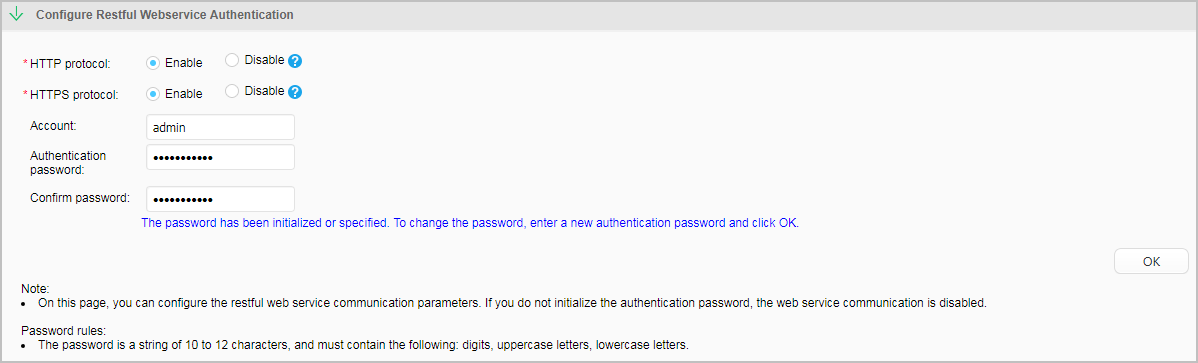
Click Configure Restful Webservice Authentication, enable HTTP protocol and HTTPS protocol, set Account to admin, and set Authentication password and Confirm password to Huawei@2018. After setting the parameters, click OK.
- Configure the CIS.
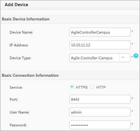
Return to the CIS homepage and choose . On the Device tab page, click Add and configure the Agile Controller-Campus information. The user name and password must be the same as those configured on the Agile Controller-Campus. After setting the parameters, click Save.
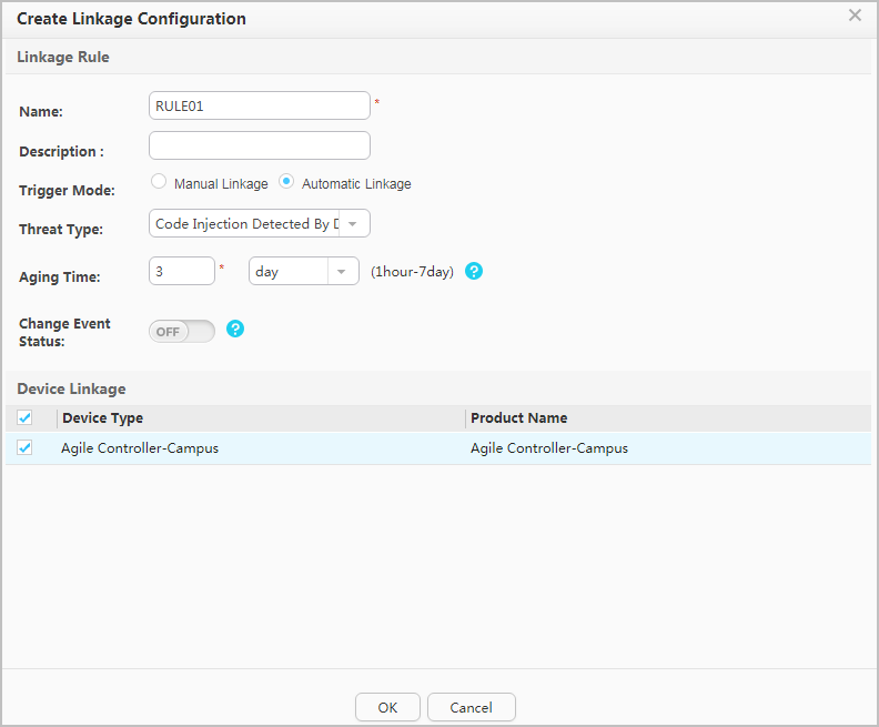
Choose Linkage Rule Conf from the navigation tree. On the Linkage Rule tab page, click Create to create an associated rule. Configure the rule based on your networking requirements and click OK.
- Select the new associated rule and click On.
- Configure the Agile Controller-Campus.
- Configure parameters used by the Agile Controller-Campus
to deliver associated policies to the DecoySensor.
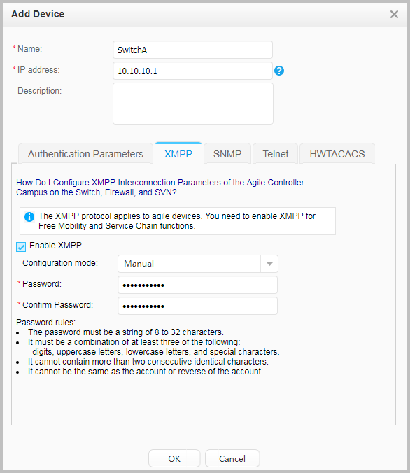
# Choose , click Add, click XMPP, specify the name and IP address of the DecoySensor, select Enable XMPP, and configure the Configuration mode to Manual. The IP address and password must be the same as those in the free mobility configuration on the switch. After setting the parameters, click OK.
- Verify the configuration.
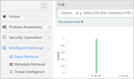
- View the lured traffic.
# Log in to the CIS and choose to view the deception events.
- Check whether the CIS has delivered the associated rule
to the Agile Controller-Campus.
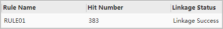
# Log in to the CIS, choose , and click the Results tab. If Linkage Status is displayed Linkage Success, the CIS has successfully delivered the associated rule to the Agile Controller-Campus. The following figure is for reference only.
- View the lured traffic.