Example for Deploying Zero Touch Devices Using an Intermediate File
Networking Requirements
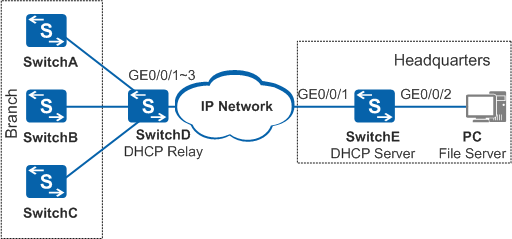
As shown in Figure 1, newly delivered devices SwitchA, SwitchB, and SwitchC are deployed in a branch and connect to GE0/0/1, GE0/0/2, and GE0/0/3 of SwitchD, respectively. SwitchD is the egress gateway of the branch and connects to the headquarters network across a Layer 3 network.
SwitchA, SwitchB, and SwitchC are different device models and need to load different system software packages, patch files, and configuration files. The enterprise wants the new devices to automatically download required version files to save labor costs of onsite configuration.
- SwitchA: Its MAC address is 0025-9e1e-773b and it needs to load the system software package s57li_easy_V200R019C10.cc (version V200R019C10SPC100), patch file s57li_easy_V200R019C10.pat, and configuration file s57li_easy_V200R019C10.cfg.
- SwitchB: Its MAC address is 0025-9e1e-773c and it needs to load the system software package s5720ei_easy_V200R019C10.cc (version V200R019C10SPC100), patch file s5720ei_easy_V200R019C10.pat, and configuration file s5720ei_easy_V200R019C10.cfg.
- SwitchC: Its MAC address is 0025-9e1e-773d and it needs to load the system software package s57li_easy_V200R019C10.cc (version V200R019C10SPC100), patch file s57li_easy_V200R019C10.pat, and configuration file s57li_easy_V200R019C10.cfg.
Configuration Roadmap
- Configure a file server on the PC directly connected to SwitchE.
- Edit an intermediate file to enable SwitchA, SwitchB, and SwitchC to obtain their system software packages, configuration files, and patch files according to the intermediate file.
- Save the intermediate file, system software packages, patch files, and configuration files in the working directory of the file server, so that the new devices can obtain these files.
- Configure DHCP relay on the egress gateway (SwitchD) of the branch, and configure the DHCP server on SwitchE. Then the DHCP server can deliver network configuration to the zero touch devices across the Layer 3 network.
- Power on SwitchA, SwitchB, and SwitchC. They can automatically start the EasyDeploy process to load their system software, patch files, and configuration files.
Procedure
- Edit the intermediate file lswnet.cfg.
# Create a file and name it lswnet.cfg. Write the following content in the file:
mac=0025-9e1e-773b;vrpfile=s57li_easy_V200R019C10.cc;vrpver=V200R019C10SPC100;patchfile=s57li_easy_V200R019C10.pat;cfgfile=s57li_easy_V200R019C10.cfg;
mac=0025-9e1e-773c;vrpfile=s5720ei_easy_V200R019C10.cc;vrpver=V200R019C10SPC100;patchfile=s5720ei_easy_V200R019C10.pat;cfgfile=s5720ei_easy_V200R019C10.cfg;
mac=0025-9e1e-773d;vrpfile=s57li_easy_V200R019C10.cc;vrpver=V200R019C10SPC100;patchfile=s57li_easy_V200R019C10.pat;cfgfile=s57li_easy_V200R019C10.cfg;
- Configure the file server.
Configure the file server according to the server manual.
After completing the configuration, save the required files on the file server.
- Configure SwitchD.
# Configure DHCP relay.
<HUAWEI> system-view
[HUAWEI] sysname DHCP_Relay
[DHCP_Relay] dhcp enable
[DHCP_Relay] vlan 10
[DHCP_Relay-vlan10] quit
[DHCP_Relay] interface gigabitethernet 0/0/1
[DHCP_Relay-GigabitEthernet0/0/1] port link-type hybrid
[DHCP_Relay-GigabitEthernet0/0/1] port hybrid pvid vlan 10
[DHCP_Relay-GigabitEthernet0/0/1] port hybrid untagged vlan 10
[DHCP_Relay-GigabitEthernet0/0/1] quit
[DHCP_Relay] interface gigabitethernet 0/0/2
[DHCP_Relay-GigabitEthernet0/0/2] port link-type hybrid
[DHCP_Relay-GigabitEthernet0/0/2] port hybrid pvid vlan 10
[DHCP_Relay-GigabitEthernet0/0/2] port hybrid untagged vlan 10
[DHCP_Relay-GigabitEthernet0/0/2] quit
[DHCP_Relay] interface gigabitethernet 0/0/3
[DHCP_Relay-GigabitEthernet0/0/3] port link-type hybrid
[DHCP_Relay-GigabitEthernet0/0/3] port hybrid pvid vlan 10
[DHCP_Relay-GigabitEthernet0/0/3] port hybrid untagged vlan 10
[DHCP_Relay-GigabitEthernet0/0/3] quit
[DHCP_Relay] interface vlanif 10
[DHCP_Relay-Vlanif10] ip address 192.168.1.6 255.255.255.0
[DHCP_Relay-Vlanif10] dhcp select relay
[DHCP_Relay-Vlanif10] dhcp relay server-ip 192.168.2.6
[DHCP_Relay-Vlanif10] quit
# Configure a static route. Set the destination IP address of the route to the PC's IP address, and the next hop to the IP address of the interface on the Layer 3 network directly connected to SwitchD.
- Configure SwitchE.
# Configure the DHCP server.
<HUAWEI> system-view
[HUAWEI] sysname DHCP_Server
[DHCP_Server] dhcp enable
[DHCP_Server] vlan batch 20 30
[DHCP_Server] interface gigabitethernet 0/0/1
[DHCP_Server-GigabitEthernet0/0/1] port link-type trunk
[DHCP_Server-GigabitEthernet0/0/1] port trunk allow-pass vlan 20
[DHCP_Server-GigabitEthernet0/0/1] quit
[DHCP_Server] interface gigabitethernet 0/0/2
[DHCP_Server-GigabitEthernet0/0/2] port link-type hybrid
[DHCP_Server-GigabitEthernet0/0/2] port hybrid pvid vlan 30
[DHCP_Server-GigabitEthernet0/0/2] port hybrid untagged vlan 30
[DHCP_Server-GigabitEthernet0/0/2] quit
[DHCP_Server] interface vlanif 20
[DHCP_Server-Vlanif20] ip address 192.168.2.6 255.255.255.0
[DHCP_Server-Vlanif20] dhcp select global
[DHCP_Server-Vlanif20] quit
[DHCP_Server] interface vlanif 30
[DHCP_Server-Vlanif30] ip address 192.168.4.1 255.255.255.0
[DHCP_Server-Vlanif30] quit
[DHCP_Server] ip pool easy-operation
[DHCP_Server-ip-pool-easy-operation] network 192.168.1.0 mask 255.255.255.0
[DHCP_Server-ip-pool-easy-operation] gateway-list 192.168.1.6
[DHCP_Server-ip-pool-easy-operation] option 141 ascii user
[DHCP_Server-ip-pool-easy-operation] option 142 cipher huawei
[DHCP_Server-ip-pool-easy-operation] option 143 ip-address 192.168.4.6
[DHCP_Server-ip-pool-easy-operation] option 146 ascii opervalue=1;delaytime=0;netfile=lswnet.cfg;
[DHCP_Server-ip-pool-easy-operation] quit
# Configure a static route. Set the destination IP address of the route to the network segment in the IP address pool configured on SwitchD, and the next hop to the IP address of the interface on the Layer 3 network directly connected to SwitchE.
- Power on SwitchA, SwitchB, and SwitchC to start the EasyDeploy process.
- Verify the configuration.# After the EasyDeploy process ends, log in to the new devices and run the display startup command to check the startup system software, configuration file, and patch file. The command output on SwitchB is used as an example.
<HUAWEI> display startup
MainBoard:
  Configured startup system software:        flash:/s5720ei_easy_V200R019C10.cc
  Startup system software:                   flash:/s5720ei_easy_V200R019C10.cc
  Next startup system software:              flash:/s5720ei_easy_V200R019C10.cc
  Startup saved-configuration file:          flash:/s5720ei_easy_V200R019C10.cfg
  Next startup saved-configuration file:     flash:/s5720ei_easy_V200R019C10.cfg
  Startup paf file:                          NULL
  Next startup paf file:                     NULL
  Startup license file:                      NULL
  Next startup license file:                 NULL
  Startup patch package:                     flash:/s5720ei_easy_V200R019C10.pat
  Next startup patch package:                flash:/s5720ei_easy_V200R019C10.pat
Configuration Files
DHCP relay agent configuration file
#
sysname DHCP_Relay
#
vlan batch 10
#
dhcp enable
#
interface Vlanif10
 ip address 192.168.1.6 255.255.255.0
 dhcp select relay
 dhcp relay server-ip 192.168.2.6
#
interface GigabitEthernet0/0/1
 port link-type hybrid
 port hybrid pvid vlan 10
 port hybrid untagged vlan 10
#
interface GigabitEthernet0/0/2
 port link-type hybrid
 port hybrid pvid vlan 10
 port hybrid untagged vlan 10
#
interface GigabitEthernet0/0/3
 port link-type hybrid
 port hybrid pvid vlan 10
 port hybrid untagged vlan 10
#
return
DHCP server configuration file
#
sysname DHCP_Server
#
vlan batch 20 30
#
dhcp enable
#
ip pool easy-operation
 gateway-list 192.168.1.6
 network 192.168.1.0 mask 255.255.255.0
 option 141 ascii user
 option 142 cipher %^%#2RC4@B`rZ/{##$1x03%Eh&S.)l7zcQUDl6MLPS"$%^%#
 option 143 ip-address 192.168.4.6
 option 146 ascii opervalue=1;delaytime=0;netfile=lswnet.cfg;
#
interface Vlanif20
 ip address 192.168.2.6 255.255.255.0
 dhcp select global
#
interface Vlanif30
 ip address 192.168.4.1 255.255.255.0
#
interface GigabitEthernet0/0/1
 port link-type trunk
 port trunk allow-pass vlan 20
#
interface GigabitEthernet0/0/2
 port link-type hybrid
 port hybrid pvid vlan 30
 port hybrid untagged vlan 30
#
return