Example for Configuring Synchronous Ethernet
Networking Requirements
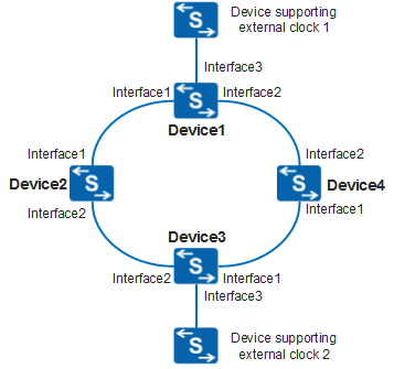
In Figure 1, devices on the clock synchronization network are connected to each other, forming a ring topology. To ensure reliability on the clock synchronization network, Device1 and Device3 each are connected to an external clock source to import clock signals. During network deployment, each device preferentially traces clock signals sent from Device1. When the clock source connected to Device1 is faulty, devices trace clock signals sent from Device3.
To ensure that devices can trace clock signals with the best quality, each device is configured with an SSM quality level that is used for clock source selection.

In this example, interface1, interface2, and interface3 are XGigabitEthernet0/0/1, XGigabitEthernet0/0/2, and XGigabitEthernet0/0/3.
An example of the devices that support external clock interfaces is S12700.
Device |
Current Clock Source |
Priority |
SSM Quality Level |
|---|---|---|---|
Device1 |
XGigabitEthernet0/0/1 |
2 |
- |
XGigabitEthernet0/0/2 |
- |
- |
|
XGigabitEthernet0/0/3 |
1 |
ssua |
|
| Device2 |
XGigabitEthernet0/0/1 |
1 |
- |
XGigabitEthernet0/0/2 |
2 |
- |
|
Device3 |
XGigabitEthernet0/0/1 |
- |
- |
XGigabitEthernet0/0/2 |
3 |
- |
|
XGigabitEthernet0/0/3 |
1 |
ssub |
|
Device4 |
XGigabitEthernet0/0/1 |
1 |
- |
XGigabitEthernet0/0/2 |
2 |
- |
Configuration Roadmap
The configuration roadmap is as follows:
- Configure a clock source.
- Configure automatic clock source selection and enable the use of SSM quality level to participate in clock source selection.
- Simulate a fault of the external clock connected to Device1 to check clock switching of the devices.
Procedure
- Configure a clock source.
# Configure Device1 to connect to the line clock source through Ethernet interfaces.
<HUAWEI> system-view
[HUAWEI] sysname Device1
[Device1] clock ethernet-synchronization enable
[Device1] interface XGigabitEthernet 0/0/1
[Device1-XGigabitEthernet0/0/1] clock synchronization enable
[Device1-XGigabitEthernet0/0/1] clock priority 2
[Device1-XGigabitEthernet0/0/1] quit
[Device1] interface XGigabitEthernet 0/0/2
[Device1-XGigabitEthernet0/0/2] clock synchronization enable
[Device1-XGigabitEthernet0/0/2] quit
[Device1] interface XGigabitEthernet 0/0/3
[Device1-XGigabitEthernet0/0/3] clock synchronization enable
[Device1-XGigabitEthernet0/0/3] clock ssm ssua
[Device1-XGigabitEthernet0/0/3] clock priority 1
[Device1-XGigabitEthernet0/0/3] quit
# Configure Device2 to connect to a line clock source through Ethernet interfaces. The configuration of Device4 is similar to the configuration of Device2, and is not mentioned here.<HUAWEI> system-view [HUAWEI] sysname Device2 [Device2] clock ethernet-synchronization enable [Device2] interface XGigabitEthernet 0/0/1 [Device2-XGigabitEthernet0/0/1] clock synchronization enable [Device2-XGigabitEthernet0/0/1] clock priority 1 [Device2-XGigabitEthernet0/0/1] quit [Device2] interface XGigabitEthernet 0/0/2 [Device2-XGigabitEthernet0/0/2] clock synchronization enable [Device2-XGigabitEthernet0/0/2] clock priority 2 [Device2-XGigabitEthernet0/0/2] quit
# Configure Device3.<HUAWEI> system-view [HUAWEI] sysname Device3 [Device3] clock ethernet-synchronization enable [Device3] interface XGigabitEthernet 0/0/1 [Device3-XGigabitEthernet0/0/1] clock synchronization enable [Device3-XGigabitEthernet0/0/1] quit [Device3] interface XGigabitEthernet 0/0/2 [Device3-XGigabitEthernet0/0/2] clock synchronization enable [Device3-XGigabitEthernet0/0/2] clock priority 3 [Device3-XGigabitEthernet0/0/2] quit [Device3] interface XGigabitEthernet 0/0/3 [Device3-XGigabitEthernet0/0/3] clock synchronization enable [Device3-XGigabitEthernet0/0/3] clock ssm ssub [Device3-XGigabitEthernet0/0/3] clock priority 1 [Device3-XGigabitEthernet0/0/3] quit
- Configure automatic clock source selection and enable the use of SSM quality level to participate in clock source selection.
# Configure Device1. The configurations of other devices are similar to the configuration of Device1, and are not mentioned here.
[Device1] clock clear slot 0         //If a clock source has been manually or forcibly specified, running this command will restore automatic clock source selection. Otherwise, this step is not required.
[Device1] clock ssm-control on
[Device1] clock run-mode normal slot 0
- Verify the configuration.
Run the display clock source command on Device1, Device2, Device3, and Device4 to check the clock sources traced by each device and the status of these clock sources.
# Check result on Device1
[Device1] display clock source
  System trace source State:   lock mode
                               into pull-in range
  Current system trace source: XGE0/0/3
  Frequency lock success:      yes

  Slot 0
  Source        Pri(sys) In-SSM   Out-SSM     State        Ref Source
  XGE0/0/1       2         dnu      sec       initial        Yes
  XGE0/0/2       ---       dnu      sec       initial        No
  XGE0/0/3       1         ssua     sec       initial        Yes
# Check result on Device2
[Device2] display clock source
  System trace source State:   lock mode
                               into pull-in range
  Current system trace source: XGE0/0/1
  Frequency lock success:      yes

  Slot 0
  Source        Pri(sys)   In-SSM   Out-SSM   State          Ref Source
  ------------------------------------------------------------------------------
  XGE0/0/1       1          ssua     dnu       normal         Yes
  XGE0/0/2       2          dnu      ssua      normal         Yes
# Check result on Device3
[Device3] display clock source
  System trace source State:   lock mode
                               into pull-in range
  Current system trace source: XGE0/0/2
  Frequency lock success:      yes

  Slot 0
  Source        Pri(sys)   In-SSM   Out-SSM   State          Ref Source
  ------------------------------------------------------------------------------
  XGE0/0/1       ---        dnu      ssua      normal         No
  XGE0/0/2       3          ssua     dnu       normal         Yes
  XGE0/0/3       1          ssub     ssua      normal         Yes
# Check result on Device4
[Device4] display clock source System trace source State: lock mode into pull-in range Current system trace source: XGE0/0/1 Frequency lock success: yes Slot 0 Source Pri(sys) In-SSM Out-SSM State Ref Source ------------------------------------------------------------------------------ XGE0/0/1 1 ssua dnu normal Yes XGE0/0/2 2 dnu ssua normal Yes - Change the SSM quality level of the external clock connected to Device1. Run the display clock source command on Device1, Device2, Device3, and Device4 to check the clock sources traced by each device and the status of
these clock sources.
[Device1] interface XGigabitEthernet 0/0/3
[Device1-XGigabitEthernet0/0/3] clock ssm sec
# On Device1, run the display clock source command to check that Device1 traces clock signals transmitted from Device3.
[Device1] display clock source
  System trace source State:   lock mode
                               into pull-in range
  Current system trace source: XGE0/0/1
  Frequency lock success:      yes

  Slot 0
  Source        Pri(sys)   In-SSM   Out-SSM   State          Ref Source
  ------------------------------------------------------------------------------
  XGE0/0/1       2          ssub     dnu       normal         Yes
  XGE0/0/3       1          sec      --        normal         Yes
# On Device2, run the display clock source command to check that Device2 traces clock signals transmitted from Device3.
[Device2] display clock source
  System trace source State:   lock mode
                               into pull-in range
  Current system trace source: XGE0/0/2
  Frequency lock success:      yes

  Slot 0
  Source        Pri(sys)   In-SSM   Out-SSM   State          Ref Source
  ------------------------------------------------------------------------------
  XGE0/0/1       1          dnu      ssub      normal         Yes
  XGE0/0/2       2          ssub     dnu       normal         Yes
# On Device3, run the display clock source command to check that Device3 traces clock signals transmitted from the external BITS source.
[Device3] display clock source
  System trace source State:   lock mode
                               into pull-in range
  Current system trace source: XGE0/0/3
  Frequency lock success:      yes

  Slot 0
  Source        Pri(sys)   In-SSM   Out-SSM   State          Ref Source
  ------------------------------------------------------------------------------
  XGE0/0/1       ---        dnu      ssub      normal         No
  XGE0/0/2       3          dnu      ssub      normal         Yes
  XGE0/0/3       1          ssub     dnu       normal         Yes
# On Device4, run the display clock source command to check that Device4 traces clock signals transmitted from Device3.
[Device4] display clock source
  System trace source State:   lock mode
                               into pull-in range
  Current system trace source: XGE0/0/1
  Frequency lock success:      yes

  Slot 0
  Source        Pri(sys)   In-SSM   Out-SSM   State          Ref Source
  ------------------------------------------------------------------------------
  XGE0/0/1       1          ssub     dnu       normal         Yes
  XGE0/0/2       2          dnu      ssub      normal         Yes
Configuration Files
Device1 configuration file
#
sysname Device1
#
clock ethernet-synchronization enable
#
interface XGigabitEthernet0/0/1
 clock priority 2
 clock synchronization enable
#
interface XGigabitEthernet0/0/2
 clock synchronization enable
#
interface XGigabitEthernet0/0/3
 clock ssm ssua
 clock priority 1
 clock synchronization enable
#
return
Device2 configuration file
#
sysname Device2
#
clock ethernet-synchronization enable
#
interface XGigabitEthernet0/0/1
 clock priority 1
 clock synchronization enable
#
interface XGigabitEthernet0/0/2
 clock priority 2
 clock synchronization enable
#
return
Device3 configuration file
#
sysname Device3
#
clock ethernet-synchronization enable
#
interface XGigabitEthernet0/0/1
 clock synchronization enable
#
interface XGigabitEthernet0/0/2
 clock priority 3
 clock synchronization enable
#
interface XGigabitEthernet0/0/3
 clock ssm ssub
 clock priority 1
 clock synchronization enable
#
return
Device4 configuration file
#
sysname Device4
#
clock ethernet-synchronization enable
#
interface XGigabitEthernet0/0/1
 clock priority 1
 clock synchronization enable
#
interface XGigabitEthernet0/0/2
 clock priority 2
 clock synchronization enable
#
return