Configuring Association Between EFM and Interfaces
Context
A device that carries IP services is usually dual-homed to an IP network to improve network robustness and service reliability. In Figure 1, CE1 is dual-homed to CE2 and CE4. EFM is deployed on the link between CE1 and CE4. When EFM detects that link quality deteriorates or a link fails, association between EFM and interfaces is triggered and services are rapidly switched to a backup link.
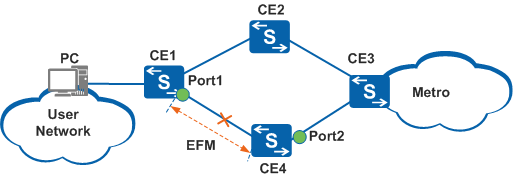
Table 1 lists association between EFM and interfaces and its usage scenarios.

A physical interface associated with EFM cannot be the one that EFM monitors. If EFM is associated with a physical interface that it monitors, the link is locked.
| Triggering Mode | Usage Scenario | Description | |
|---|---|---|---|
Link fault |
In Figure 1, when EFM detects that the link between CE1 and CE4 becomes faulty (the EFM status changes from Detect to Discovery), association between EFM and EFM-capable Port1 is triggered and traffic is switched from the primary path CE1-CE4 to the backup path CE1-CE2. |
The association function is configured in the interface view and is unidirectional. That is, EFM is associated with an interface only when EFM detects a fault on the link. If EFM detects a link fault, the protocol status of the interface associated with EFM is set to ETHOAM Down. Only EFM OAMPDUs can be transmitted, speeding up route convergence. In addition, services can be switched from the primary path to the backup path. |
|
In Figure 1, when EFM detects that the link between CE1 and CE4 becomes faulty, association between EFM and EFM-incapable Port2 is triggered and traffic is switched from the path CE3-CE4 to the path CE3-CE2.
|
The association function is configured in the MGR view and is bidirectional.
|
||
Threshold crossing event |
In Figure 1, EFM is used to monitor links. If an errored code event, errored frame event, or errored frame second event occurs on a link, the link quality is considered low. Association between EFM and interfaces is triggered to implement a rapid active/standby link switchover, ensuring reliable traffic transmission. | After a threshold crossing event is associated with an interface, the system sets the administrative status of the interface to Down. In this manner, all services on the interface are interrupted. |
|
Remote fault |
In Figure 1, when EFM detects link-fault, dying-gasp, or critical-event faults, association between EFM and interfaces is triggered to implement a rapid active/standby link switchover, ensuring reliable traffic transmission. | After a remote fault is associated with an interface, the system sets the administrative status of the interface to Down. In this manner, all services on the interface are interrupted. Traffic will not be switched back even if the faulty link recovers and the protocol status of the interface does not change. You need to manually check link quality before switching traffic back to the original link. |
|
EFM can be configured on Layer 2 and Layer 3 Ethernet interfaces. By default, an Ethernet interface works in Layer 2 mode. Before configuring EFM on a Layer 3 Ethernet interface, switch the Ethernet interface to Layer 3 mode.
Pre-configuration Tasks
Before associating EFM OAM with interfaces, perform the task of Configuring Basic EFM Functions.
Procedure
- Configure association between EFM and interfaces to be triggered by a link fault.
Configure association between EFM and EFM-capable interfaces.
Run system-view
The system view is displayed.
Run interface interface-type interface-number
The view of the interface at one end of the link is displayed.
(Optional) On an Ethernet interface, run undo portswitch
The interface is switched to Layer 3 mode.
By default, an Ethernet interface works in Layer 2 mode.

Only the S5720-EI, S5720-HI, S5730-HI, S5731-H, S5731-S, S5731S-H, S5731S-S, S5732-H, S6720-EI, S6720-HI, S6720S-EI, S6730-H, S6730S-H, S6730-S, and S6730S-S support switching between Layer 2 and Layer 3 modes.
Run efm trigger if-down
The interface is associated with EFM.
By default, EFM OAM is not associated with any interface.
Before associating EFM with an interface, you must enable EFM on the interface using the efm enable command.
In addition, you can configure association between EFM and an interface only after EFM at both ends are in Detect state.
If Layer 2 and Layer 3 services are blocked due to a misoperation, run the undo efm trigger if-down command in the interface view to restore services.
(Optional) Run efm holdup-timer time
The EFM faulty-state holdup timer is set.
By default, the value of the EFM faulty-state holdup timer is 0s.
After the efm trigger if-down command is used to associate EFM OAM with an interface, when EFM OAM detects a connectivity fault, the faulty state remains unchanged within the EFM faulty-state holdup timer. After the EFM faulty-state holdup time expires, EFM starts to check whether the link fault is rectified. This mechanism prevents the interface from alternating between Up and Down states due to link instability.
Configure association between EFM and an EFM-incapable interface.
Run oam-mgr
The OAM management view is displayed.
Run oam-bind ingress efm interface interface-type1 interface-number1 trigger if-down egress interface interface-type2 interface-number2
EFM is configured to notify the interface of faults.
Run oam-bind ingress interface interface-type1 interface-number1 egress efm interface interface-type2 interface-number2 trigger if-down
The interface is configured to notify EFM of faults.
Run oam-bind efm interface interface-type1 interface-number1 trigger if-down interface interface-type2 interface-number2
EFM and the interface are configured to notify each other of faults.
For details on the relationship and usage of the three commands, see oam-bind efm interface interface-type1 interface-number1 trigger if-down interface interface-type2 interface-number2.
If the oam-bind efm interface interface-type1 interface-number1 trigger if-down interface interface-type2 interface-number2 command is run, the oam-bind ingress efm interface interface-type1 interface-number1 trigger if-down egress interface interface-type2 interface-number2 and oam-bind ingress interface interface-type1 interface-number1 egress efm interface interface-type2 interface-number2 trigger if-down commands used to configure association functions in opposite directions will be displayed in the configuration file.
- Configure association between EFM and interfaces to be triggered by a minor link event.
For details, see Configuring EFM Link Monitoring.
- Configure association between EFM and interfaces to be triggered by a remote fault.
For details, see Configuring Remote Fault Indication.