Example for Configuring ERPS Multi-instance
Networking Requirements
Generally, redundant links are used on an Ethernet switching network to provide link backup and enhance network reliability. The use of redundant links, however, may produce loops, causing broadcast storms and rendering the MAC address table unstable. As a result, communication quality deteriorates, and communication services may even be interrupted.
To prevent loops caused by redundant links, enable ERPS on the nodes of the ring network. ERPS is a Layer 2 loop-breaking protocol defined by the ITU-T, and provides fast convergence of carrier-class reliability standards.
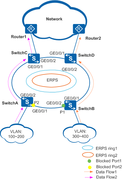
Figure 1 shows a network on which a multi-instance ERPS ring is used. SwitchA through SwitchD constitute a ring network at the aggregation layer to implement service aggregation at Layer 2 and process Layer 3 services. ERPS is used on the ring network to provide protection switching for Layer 2 redundant links. ERPS ring 1 and ERPS ring 2 are configured on SwitchA through SwitchD. P1 on SwitchB is a blocked port in ERPS ring 1, and P2 on SwitchA is a blocked port in ERPS ring 2, implementing load balancing and link backup.
Configuration Roadmap
The configuration roadmap is as follows:
Configure the link type of all ports to be added to ERPS rings as trunk.
Create ERPS rings and configure control VLANs and Ethernet Ring Protection (ERP) instances in the ERPS rings.
Add Layer 2 ports to ERPS rings and specify port roles.
Configure the Guard timers and WTR timers in the ERPS rings.
Configure Layer 2 forwarding on SwitchA through SwitchD.
Procedure
- Configure the link type of all ports to be added to an ERPS ring as trunk.
# Configure SwitchA.
<HUAWEI> system-view
[HUAWEI] sysname SwitchA
[SwitchA] interface gigabitethernet 0/0/1
[SwitchA-GigabitEthernet0/0/1] port link-type trunk
[SwitchA-GigabitEthernet0/0/1] quit
[SwitchA] interface gigabitethernet 0/0/2
[SwitchA-GigabitEthernet0/0/2] port link-type trunk
[SwitchA-GigabitEthernet0/0/2] quit
# Configure SwitchB.
<HUAWEI> system-view
[HUAWEI] sysname SwitchB
[SwitchB] interface gigabitethernet 0/0/1
[SwitchB-GigabitEthernet0/0/1] port link-type trunk
[SwitchB-GigabitEthernet0/0/1] quit
[SwitchB] interface gigabitethernet 0/0/2
[SwitchB-GigabitEthernet0/0/2] port link-type trunk
[SwitchB-GigabitEthernet0/0/2] quit
# Configure SwitchC.
<HUAWEI> system-view
[HUAWEI] sysname SwitchC
[SwitchC] interface gigabitethernet 0/0/1
[SwitchC-GigabitEthernet0/0/1] port link-type trunk
[SwitchC-GigabitEthernet0/0/1] quit
[SwitchC] interface gigabitethernet 0/0/2
[SwitchC-GigabitEthernet0/0/2] port link-type trunk
[SwitchC-GigabitEthernet0/0/2] quit
# Configure SwitchD.
<HUAWEI> system-view
[HUAWEI] sysname SwitchD
[SwitchD] interface gigabitethernet 0/0/1
[SwitchD-GigabitEthernet0/0/1] port link-type trunk
[SwitchD-GigabitEthernet0/0/1] quit
[SwitchD] interface gigabitethernet 0/0/2
[SwitchD-GigabitEthernet0/0/2] port link-type trunk
[SwitchD-GigabitEthernet0/0/2] quit
- Create ERPS ring 1 and ERPS ring 2 and configure ERP instances in the two rings. Set the control VLAN ID of ERPS ring 1 to 10 and the control VLAN ID of ERPS ring 2 to 20. Enable ERPS ring 1 to transmit data packets from VLANs 100 to 200 and enable ERPS ring 2 to transmit data packets from VLANs 300 to 400.
# Configure SwitchA.
[SwitchA] erps ring 1
[SwitchA-erps-ring1] control-vlan 10
[SwitchA-erps-ring1] protected-instance 1
[SwitchA-erps-ring1] quit
[SwitchA] stp region-configuration
[SwitchA-mst-region] instance 1 vlan 10 100 to 200
[SwitchA-mst-region] active region-configuration
[SwitchA-mst-region] quit
[SwitchA] erps ring 2
[SwitchA-erps-ring2] control-vlan 20
[SwitchA-erps-ring2] protected-instance 2
[SwitchA-erps-ring2] quit
[SwitchA] stp region-configuration
[SwitchA-mst-region] instance 2 vlan 20 300 to 400
[SwitchA-mst-region] active region-configuration
[SwitchA-mst-region] quit
# Configure SwitchB.
[SwitchB] erps ring 1
[SwitchB-erps-ring1] control-vlan 10
[SwitchB-erps-ring1] protected-instance 1
[SwitchB-erps-ring1] quit
[SwitchB] stp region-configuration
[SwitchB-mst-region] instance 1 vlan 10 100 to 200
[SwitchB-mst-region] active region-configuration
[SwitchB-mst-region] quit
[SwitchB] erps ring 2
[SwitchB-erps-ring2] control-vlan 20
[SwitchB-erps-ring2] protected-instance 2
[SwitchB-erps-ring2] quit
[SwitchB] stp region-configuration
[SwitchB-mst-region] instance 2 vlan 20 300 to 400
[SwitchB-mst-region] active region-configuration
[SwitchB-mst-region] quit
# Configure SwitchC.
[SwitchC] erps ring 1
[SwitchC-erps-ring1] control-vlan 10
[SwitchC-erps-ring1] protected-instance 1
[SwitchC-erps-ring1] quit
[SwitchC] stp region-configuration
[SwitchC-mst-region] instance 1 vlan 10 100 to 200
[SwitchC-mst-region] active region-configuration
[SwitchC-mst-region] quit
[SwitchC] erps ring 2
[SwitchC-erps-ring2] control-vlan 20
[SwitchC-erps-ring2] protected-instance 2
[SwitchC-erps-ring2] quit
[SwitchC] stp region-configuration
[SwitchC-mst-region] instance 2 vlan 20 300 to 400
[SwitchC-mst-region] active region-configuration
[SwitchC-mst-region] quit
# Configure SwitchD.
[SwitchD] erps ring 1
[SwitchD-erps-ring1] control-vlan 10
[SwitchD-erps-ring1] protected-instance 1
[SwitchD-erps-ring1] quit
[SwitchD] stp region-configuration
[SwitchD-mst-region] instance 1 vlan 10 100 to 200
[SwitchD-mst-region] active region-configuration
[SwitchD-mst-region] quit
[SwitchD] erps ring 2
[SwitchD-erps-ring2] control-vlan 20
[SwitchD-erps-ring2] protected-instance 2
[SwitchD-erps-ring2] quit
[SwitchD] stp region-configuration
[SwitchD-mst-region] instance 2 vlan 20 300 to 400
[SwitchD-mst-region] active region-configuration
[SwitchD-mst-region] quit
- Add Layer 2 ports to ERPS rings and specify port roles. Configure GE 0/0/1 on SwitchA and GE 0/0/2 on SwitchB as their respective RPL owner ports.
# Configure SwitchA.
[SwitchA] interface gigabitethernet 0/0/1
[SwitchA-GigabitEthernet0/0/1] stp disable
[SwitchA-GigabitEthernet0/0/1] erps ring 1
[SwitchA-GigabitEthernet0/0/1] erps ring 2 rpl owner
[SwitchA-GigabitEthernet0/0/1] quit
[SwitchA] interface gigabitethernet 0/0/2
[SwitchA-GigabitEthernet0/0/2] stp disable
[SwitchA-GigabitEthernet0/0/2] erps ring 1
[SwitchA-GigabitEthernet0/0/2] erps ring 2
[SwitchA-GigabitEthernet0/0/2] quit
# Configure SwitchB.
[SwitchB] interface gigabitethernet 0/0/1
[SwitchB-GigabitEthernet0/0/1] stp disable
[SwitchB-GigabitEthernet0/0/1] erps ring 1
[SwitchB-GigabitEthernet0/0/1] erps ring 2
[SwitchB-GigabitEthernet0/0/1] quit
[SwitchB] interface gigabitethernet 0/0/2
[SwitchB-GigabitEthernet0/0/2] stp disable
[SwitchB-GigabitEthernet0/0/2] erps ring 1 rpl owner
[SwitchB-GigabitEthernet0/0/2] erps ring 2
[SwitchB-GigabitEthernet0/0/2] quit
# Configure SwitchC.
[SwitchC] interface gigabitethernet 0/0/1
[SwitchC-GigabitEthernet0/0/1] stp disable
[SwitchC-GigabitEthernet0/0/1] erps ring 1
[SwitchC-GigabitEthernet0/0/1] erps ring 2
[SwitchC-GigabitEthernet0/0/1] quit
[SwitchC] interface gigabitethernet 0/0/2
[SwitchC-GigabitEthernet0/0/2] stp disable
[SwitchC-GigabitEthernet0/0/2] erps ring 1
[SwitchC-GigabitEthernet0/0/2] erps ring 2
[SwitchC-GigabitEthernet0/0/2] quit
# Configure SwitchD.
[SwitchD] interface gigabitethernet 0/0/1
[SwitchD-GigabitEthernet0/0/1] stp disable
[SwitchD-GigabitEthernet0/0/1] erps ring 1
[SwitchD-GigabitEthernet0/0/1] erps ring 2
[SwitchD-GigabitEthernet0/0/1] quit
[SwitchD] interface gigabitethernet 0/0/2
[SwitchD-GigabitEthernet0/0/2] stp disable
[SwitchD-GigabitEthernet0/0/2] erps ring 1
[SwitchD-GigabitEthernet0/0/2] erps ring 2
[SwitchD-GigabitEthernet0/0/2] quit
- Configure the Guard timers and WTR timers in the ERPS rings.
# Configure SwitchA.
[SwitchA] erps ring 1
[SwitchA-erps-ring1] wtr-timer 6
[SwitchA-erps-ring1] guard-timer 100
[SwitchA-erps-ring1] quit
[SwitchA] erps ring 2
[SwitchA-erps-ring2] wtr-timer 6
[SwitchA-erps-ring2] guard-timer 100
[SwitchA-erps-ring2] quit
# Configure SwitchB.
[SwitchB] erps ring 1
[SwitchB-erps-ring1] wtr-timer 6
[SwitchB-erps-ring1] guard-timer 100
[SwitchB-erps-ring1] quit
[SwitchB] erps ring 2
[SwitchB-erps-ring2] wtr-timer 6
[SwitchB-erps-ring2] guard-timer 100
[SwitchB-erps-ring2] quit
# Configure SwitchC.
[SwitchC] erps ring 1
[SwitchC-erps-ring1] wtr-timer 6
[SwitchC-erps-ring1] guard-timer 100
[SwitchC-erps-ring1] quit
[SwitchC] erps ring 2
[SwitchC-erps-ring2] wtr-timer 6
[SwitchC-erps-ring2] guard-timer 100
[SwitchC-erps-ring2] quit
# Configure SwitchD.
[SwitchD] erps ring 1
[SwitchD-erps-ring1] wtr-timer 6
[SwitchD-erps-ring1] guard-timer 100
[SwitchD-erps-ring1] quit
[SwitchD] erps ring 2
[SwitchD-erps-ring2] wtr-timer 6
[SwitchD-erps-ring2] guard-timer 100
[SwitchD-erps-ring2] quit
- Configure Layer 2 forwarding on SwitchA through SwitchD.
# Configure SwitchA.
[SwitchA] vlan batch 100 to 200 300 to 400
[SwitchA] interface gigabitethernet 0/0/1
[SwitchA-GigabitEthernet0/0/1] undo port trunk allow-pass vlan 1
[SwitchA-GigabitEthernet0/0/1] port trunk allow-pass vlan 100 to 200 300 to 400
[SwitchA-GigabitEthernet0/0/1] quit
[SwitchA] interface gigabitethernet 0/0/2
[SwitchA-GigabitEthernet0/0/2] undo port trunk allow-pass vlan 1
[SwitchA-GigabitEthernet0/0/2] port trunk allow-pass vlan 100 to 200 300 to 400
[SwitchA-GigabitEthernet0/0/2] quit
# Configure SwitchB.
[SwitchB] vlan batch 100 to 200 300 to 400
[SwitchB] interface gigabitethernet 0/0/1
[SwitchB-GigabitEthernet0/0/1] undo port trunk allow-pass vlan 1
[SwitchB-GigabitEthernet0/0/1] port trunk allow-pass vlan 100 to 200 300 to 400
[SwitchB-GigabitEthernet0/0/1] quit
[SwitchB] interface gigabitethernet 0/0/2
[SwitchB-GigabitEthernet0/0/2] undo port trunk allow-pass vlan 1
[SwitchB-GigabitEthernet0/0/2] port trunk allow-pass vlan 100 to 200 300 to 400
[SwitchB-GigabitEthernet0/0/2] quit
# Configure SwitchC.
[SwitchC] vlan batch 100 to 200 300 to 400
[SwitchC] interface gigabitethernet 0/0/1
[SwitchC-GigabitEthernet0/0/1] undo port trunk allow-pass vlan 1
[SwitchC-GigabitEthernet0/0/1] port trunk allow-pass vlan 100 to 200 300 to 400
[SwitchC-GigabitEthernet0/0/1] quit
[SwitchC] interface gigabitethernet 0/0/2
[SwitchC-GigabitEthernet0/0/2] undo port trunk allow-pass vlan 1
[SwitchC-GigabitEthernet0/0/2] port trunk allow-pass vlan 100 to 200 300 to 400
[SwitchC-GigabitEthernet0/0/2] quit
# Configure SwitchD.
[SwitchD] vlan batch 100 to 200 300 to 400
[SwitchD] interface gigabitethernet 0/0/1
[SwitchD-GigabitEthernet0/0/1] undo port trunk allow-pass vlan 1
[SwitchD-GigabitEthernet0/0/1] port trunk allow-pass vlan 100 to 200 300 to 400
[SwitchD-GigabitEthernet0/0/1] quit
[SwitchD] interface gigabitethernet 0/0/2
[SwitchD-GigabitEthernet0/0/2] undo port trunk allow-pass vlan 1
[SwitchD-GigabitEthernet0/0/2] port trunk allow-pass vlan 100 to 200 300 to 400
[SwitchD-GigabitEthernet0/0/2] quit
- Verify the configuration.
# After the network becomes stable, run the display erps command to check brief information about the ERPS ring and ports added to the ERPS ring. SwitchB is used as an example.
[SwitchB] display erps
D : Discarding
F : Forwarding
R : RPL Owner
N  : RPL Neighbour
FS : Forced Switch
MS : Manual Switch
Total number of rings configured = 2
Ring  Control  WTR Timer  Guard Timer  Port 1              Port 2
ID    VLAN     (min)      (csec)
--------------------------------------------------------------------------------
   1       10          6          100  (F)GE0/0/1          (D,R)GE0/0/2
   2       20          6          100  (F)GE0/0/1          (F)GE0/0/2
--------------------------------------------------------------------------------
# Run the display erps verbose command to check detailed information about the ERPS ring and ports added to the ERPS ring. SwitchB is used as an example.
[SwitchB] display erps verbose
Ring ID                             : 1
Description                         : Ring 1
Control Vlan                        : 10
Protected Instance                  : 1
Service Vlan                        : 100 to 200
WTR Timer Setting (min)             : 6      Running (s)           : 0
Guard Timer Setting (csec)          : 100    Running (csec)        : 0
Holdoff Timer Setting (deciseconds) : 0      Running (deciseconds) : 0
WTB Timer Running (csec)            : 0
Ring State                          : Idle
RAPS_MEL                            : 7
Revertive Mode                      : Revertive
R-APS Channel Mode                  : -
Version                             : 1
Sub-ring                            : No
Forced Switch Port                  : -
Manual Switch Port                  : -
TC-Notify                           : -
Time since last topology change     : 0 days 0h:35m:5s
--------------------------------------------------------------------------------
Port                Port Role     Port Status     Signal Status
--------------------------------------------------------------------------------
GE0/0/1             Common        Forwarding      Non-failed
GE0/0/2             RPL Owner     Discarding      Non-failed

Ring ID                             : 2
Description                         : Ring 2
Control Vlan                        : 20
Protected Instance                  : 2
Service Vlan                        : 300 to 400
WTR Timer Setting (min)             : 6      Running (s)           : 0
Guard Timer Setting (csec)          : 100    Running (csec)        : 0
Holdoff Timer Setting (deciseconds) : 0      Running (deciseconds) : 0
WTB Timer Running (csec)            : 0
Ring State                          : Idle
RAPS_MEL                            : 7
Revertive Mode                      : Revertive
R-APS Channel Mode                  : -
Version                             : 1
Sub-ring                            : No
Forced Switch Port                  : -
Manual Switch Port                  : -
TC-Notify                           : -
Time since last topology change     : 0 days 0h:35m:30s
--------------------------------------------------------------------------------
Port                Port Role     Port Status     Signal Status
--------------------------------------------------------------------------------
GE0/0/1             Common        Forwarding      Non-failed
GE0/0/2             Common        Forwarding      Non-failed
Configuration Files
SwitchA configuration file
#
sysname SwitchA
#
vlan batch 10 20 100 to 200 300 to 400
#
stp region-configuration
 instance 1 vlan 10 100 to 200
 instance 2 vlan 20 300 to 400
 active region-configuration
#
erps ring 1
 control-vlan 10
 protected-instance 1
 wtr-timer 6
 guard-timer 100
erps ring 2
 control-vlan 20
 protected-instance 2
 wtr-timer 6
 guard-timer 100
#
interface GigabitEthernet0/0/1
 port link-type trunk
 undo port trunk allow-pass vlan 1
 port trunk allow-pass vlan 10 20 100 to 200 300 to 400
 stp disable
 erps ring 1
 erps ring 2 rpl owner
#
interface GigabitEthernet0/0/2
 port link-type trunk
 undo port trunk allow-pass vlan 1
 port trunk allow-pass vlan 10 20 100 to 200 300 to 400
 stp disable
 erps ring 1
 erps ring 2
#
return
SwitchB configuration file
#
sysname SwitchB
#
vlan batch 10 20 100 to 200 300 to 400
#
stp region-configuration
 instance 1 vlan 10 100 to 200
 instance 2 vlan 20 300 to 400
 active region-configuration
#
erps ring 1
 control-vlan 10
 protected-instance 1
 wtr-timer 6
 guard-timer 100
erps ring 2
 control-vlan 20
 protected-instance 2
 wtr-timer 6
 guard-timer 100
#
interface GigabitEthernet0/0/1
 port link-type trunk
 undo port trunk allow-pass vlan 1
 port trunk allow-pass vlan 10 20 100 to 200 300 to 400
 stp disable
 erps ring 1
 erps ring 2
#
interface GigabitEthernet0/0/2
 port link-type trunk
 undo port trunk allow-pass vlan 1
 port trunk allow-pass vlan 10 20 100 to 200 300 to 400
 stp disable
 erps ring 1 rpl owner
 erps ring 2
#
return
SwitchC configuration file
#
sysname SwitchC
#
vlan batch 10 20 100 to 200 300 to 400
#
stp region-configuration
 instance 1 vlan 10 100 to 200
 instance 2 vlan 20 300 to 400
 active region-configuration
#
erps ring 1
 control-vlan 10
 protected-instance 1
 wtr-timer 6
 guard-timer 100
erps ring 2
 control-vlan 20
 protected-instance 2
 wtr-timer 6
 guard-timer 100
#
interface GigabitEthernet0/0/1
 port link-type trunk
 undo port trunk allow-pass vlan 1
 port trunk allow-pass vlan 10 20 100 to 200 300 to 400
 stp disable
 erps ring 1
 erps ring 2
#
interface GigabitEthernet0/0/2
 port link-type trunk
 undo port trunk allow-pass vlan 1
 port trunk allow-pass vlan 10 20 100 to 200 300 to 400
 stp disable
 erps ring 1
 erps ring 2
#
return
SwitchD configuration file
#
sysname SwitchD
#
vlan batch 10 20 100 to 200 300 to 400
#
stp region-configuration
 instance 1 vlan 10 100 to 200
 instance 2 vlan 20 300 to 400
 active region-configuration
#
erps ring 1
 control-vlan 10
 protected-instance 1
 wtr-timer 6
 guard-timer 100
erps ring 2
 control-vlan 20
 protected-instance 2
 wtr-timer 6
 guard-timer 100
#
interface GigabitEthernet0/0/1
 port link-type trunk
 undo port trunk allow-pass vlan 1
 port trunk allow-pass vlan 10 20 100 to 200 300 to 400
 stp disable
 erps ring 1
 erps ring 2
#
interface GigabitEthernet0/0/2
 port link-type trunk
 undo port trunk allow-pass vlan 1
 port trunk allow-pass vlan 10 20 100 to 200 300 to 400
 stp disable
 erps ring 1
 erps ring 2
#
return