Configuring the ERPS over VPLS Function
Prerequisites
- A routing protocol has been run on the PEs on the VPLS network to ensure that they can communicate.
- Basic MPLS capabilities have been configured on the VPLS network, and LDP LSPs has been established.
- VPLS connections have been established between each two PEs, and each Ethernet sub-interface or VLANIF interface has been bound to a VSI.
- Interfaces on CEs and PEs have been added to the ERPS ring.
Context
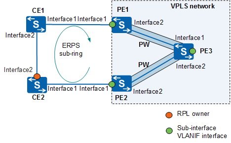
On the VPLS network shown in Figure 1, CEs are dual-homed to PEs. However, PE3 receives two copies of CE1 traffic from both PE1 and PE2. To resolve this problem, enable ERPS on CE1, CE2, PE1, and PE2 and configure CE2's interface2 as an RPL owner port to block traffic from CE1. In this way, CE1's traffic reaches PE3 over PE1 without traversing CE2, thereby preventing any duplicate traffic or loops.
In Figure 1, the ERPS ring connects to a VPLS network through Ethernet sub-interfaces or VLANIF interfaces. To ensure that the VPLS network can promptly detect topology changes of the ERPS ring, enable topology change notification on the main interface through which PE1 and PE2 access the ERPS ring.

Only the S5720-EI, S5720-HI, S5730-HI, S5731-H, S5731S-H, S5732-H, S6720-EI, S6720-HI, S6720S-EI, S6730S-H, S6730-H support this function.
Procedure
- Run system-view
The system view is displayed.
- Run interface interface-type interface-number
The interface view is displayed.
- Run erps vpls-subinterface enable
Topology change notification is enabled on the interface.
By default, the interface does not instruct VSI-bound sub-interfaces or VLANIF interfaces to update MAC address entries promptly after the ERPS ring topology changes.
After topology change notification is enabled on the interface, when the forwarding status of the interface changes to Discarding, its VSI-bound sub-interfaces or member interfaces of the VLANIF interface will change to the Discarding state to prevent loops on the VPLS network on which a CE is dual-homed to PEs.