Example for Configuring ERPS over VPLS in Scenarios Where a CE Is Dual-Homed to PEs (Through Ethernet Sub-interfaces)
Networking Requirements
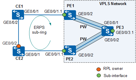
To configure ERPS over VPLS in scenarios where a CE is dual-homed to PEs, enable ERPS on CE1, CE2, PE1, and PE2 and configure the ERPS sub-ring to access the VPLS network in NVC mode. Using Ethernet sub-interfaces to access the VPLS network must have the TC notification function enabled so that the VPLS network can have ARP and MAC address entries updated promptly after receiving TC packets. On the VPLS network shown in Figure 1, CEs are dual-homed to PEs through Ethernet sub-interfaces. However, this networking will cause PE3 to receive two copies of CE1 traffic from both PE1 and PE2. To resolve this problem, enable ERPS on CE1, CE2, PE1, and PE2 and configure CE2's GE0/0/2 as an RPL owner port to block traffic from CE1. In this way, CE1's traffic reaches PE3 over PE1 without traversing CE2, thereby preventing any duplicate traffic or loops.
In Figure 1, the ERPS ring connects to a VPLS network through Ethernet sub-interfaces.

This section uses CE dual-homing scenarios as an example. The configurations of ERPS over VPLS in CE single-homing scenarios are similar to those in CE dual-homing scenarios.
The IP addresses of the interfaces on PE1, PE2, and PE3 are listed in Table 1.
Configuration Roadmap
The configuration roadmap is as follows:
Run an IGP protocol on the PEs to ensure that they can communicate on the VPLS network.
Configure basic MPLS capabilities on the VPLS network, and establish LDP LSPs.
Establish VPLS connections between each two PEs and bind each Ethernet sub-interface to a VSI.
Configure ERPS, including:
- Enable ERPS on CE1, CE2, PE1, and PE2.
- Configure CE2's GE0/0/2 as an RPL owner port.
Data Preparation
To complete the configuration, you need the following data:
Data needed for configuring OSPF: IP address of each interface, OSPF process ID, and OSPF domain ID
MPLS LSR ID (as the MPLS peer address)
VSI name and VSI ID
Names of the VSI-bound Ethernet sub-interfaces
ERPS ring ID, control VLAN ID, and RPL owner port number
Procedure
- Assign an IP address to each interface and configure an IGP on the VPLS network to allow PEs to communicate. This example uses OSPF as the IGP.
When configuring OSPF, advertise the 32-bit IP addresses of loopback interfaces, which are used as LSR IDs, on the PEs.
For configuration details, see Configuration Files in this section.
- Configure basic MPLS capabilities on the MPLS backbone network, and set up LDP LSPs among the PEs.
# Configure PE1.
[PE1] mpls lsr-id 1.1.1.1
[PE1] mpls
[PE1-mpls] quit
[PE1] mpls ldp
[PE1-mpls-ldp] quit
[PE1] interface gigabitethernet 0/0/2
[PE1-GigabitEthernet0/0/2] mpls
[PE1-GigabitEthernet0/0/2] mpls ldp
[PE1-GigabitEthernet0/0/2] quit
# Configure PE2.
[PE2] mpls lsr-id 2.2.2.2
[PE2] mpls
[PE2-mpls] quit
[PE2] mpls ldp
[PE2-mpls-ldp] quit
[PE2] interface gigabitethernet 0/0/2
[PE2-GigabitEthernet0/0/2] mpls
[PE2-GigabitEthernet0/0/2] mpls ldp
[PE2-GigabitEthernet0/0/2] quit
# Configure PE3.
[PE3] mpls lsr-id 3.3.3.3
[PE3] mpls
[PE3-mpls] quit
[PE3] mpls ldp
[PE3-mpls-ldp] quit
[PE3] interface gigabitethernet 0/0/1
[PE3-GigabitEthernet0/0/1] mpls
[PE3-GigabitEthernet0/0/1] mpls ldp
[PE3-GigabitEthernet0/0/1] quit
[PE3] interface gigabitethernet 0/0/2
[PE3-GigabitEthernet0/0/2] mpls
[PE3-GigabitEthernet0/0/2] mpls ldp
[PE3-GigabitEthernet0/0/2] quit
- Enable MPLS L2VPN on the PEs.
# Configure PE1.
[PE1] mpls l2vpn
[PE1-l2vpn] quit
# Configure PE2.
[PE2] mpls l2vpn
[PE2-l2vpn] quit
# Configure PE3.
[PE3] mpls l2vpn
[PE3-l2vpn] quit
- Configure a VPLS network.
# Configure PE1.
[PE1] vsi s1 static
[PE1-vsi-s1] pwsignal ldp
[PE1-vsi-s1-ldp] vsi-id 10
[PE1-vsi-s1-ldp] peer 3.3.3.3
[PE1-vsi-s1-ldp] quit
[PE1-vsi-s1] quit
[PE1] interface gigabitethernet 0/0/1.1
[PE1-GigabitEthernet0/0/1.1] shutdown
[PE1-GigabitEthernet0/0/1.1] dot1q termination vid 10
[PE1-GigabitEthernet0/0/1.1] l2 binding vsi s1
[PE1-GigabitEthernet0/0/1.1] undo shutdown
[PE1-GigabitEthernet0/0/1.1] quit
# Configure PE2.
[PE2] vsi s1 static
[PE2-vsi-s1] pwsignal ldp
[PE2-vsi-s1-ldp] vsi-id 10
[PE2-vsi-s1-ldp] peer 3.3.3.3
[PE2-vsi-s1-ldp] quit
[PE2-vsi-s1] quit
[PE2] interface gigabitethernet 0/0/1.1
[PE2-GigabitEthernet0/0/1.1] shutdown
[PE2-GigabitEthernet0/0/1.1] dot1q termination vid 10
[PE2-GigabitEthernet0/0/1.1] l2 binding vsi s1
[PE2-GigabitEthernet0/0/1.1] undo shutdown
[PE2-GigabitEthernet0/0/1.1] quit
# Configure PE3.
[PE3] vsi s1 static
[PE3-vsi-s1] pwsignal ldp
[PE3-vsi-s1-ldp] vsi-id 10
[PE3-vsi-s1-ldp] peer 1.1.1.1
[PE3-vsi-s1-ldp] peer 2.2.2.2
[PE3-vsi-s1-ldp] quit
[PE3-vsi-s1] quit
[PE3] interface gigabitethernet 0/0/3.1
[PE3-GigabitEthernet0/0/3.1] shutdown
[PE3-GigabitEthernet0/0/3.1] dot1q termination vid 10
[PE3-GigabitEthernet0/0/3.1] l2 binding vsi s1
[PE3-GigabitEthernet0/0/3.1] undo shutdown
[PE3-GigabitEthernet0/0/3.1] quit
- Configure ERPS on PE1, PE2, CE1, and CE2.
# Configure PE1.
[PE1] erps ring 1
[PE1-erps-ring1] control-vlan 100
[PE1-erps-ring1] protected-instance 1
[PE1-erps-ring1] version v2
[PE1-erps-ring1] sub-ring
[PE1-erps-ring1] quit
[PE1] stp region-configuration
[PE1-mst-region] instance 1 vlan 10 100
[PE1-mst-region] active region-configuration
[PE1-mst-region] quit
[PE1] interface gigabitethernet 0/0/1
[PE1-GigabitEthernet0/0/1] port link-type trunk
[PE1-GigabitEthernet0/0/1] undo port trunk allow-pass vlan 1
[PE1-GigabitEthernet0/0/1] stp disable
[PE1-GigabitEthernet0/0/1] erps ring 1
[PE1-GigabitEthernet0/0/1] erps vpls-subinterface enable
[PE1-GigabitEthernet0/0/1] quit
# Configure PE2.
[PE2] erps ring 1
[PE2-erps-ring1] control-vlan 100
[PE2-erps-ring1] protected-instance 1
[PE2-erps-ring1] version v2
[PE2-erps-ring1] sub-ring
[PE2-erps-ring1] quit
[PE2] stp region-configuration
[PE2-mst-region] instance 1 vlan 10 100
[PE2-mst-region] active region-configuration
[PE2-mst-region] quit
[PE2] interface gigabitethernet 0/0/1
[PE2-GigabitEthernet0/0/1] port link-type trunk
[PE2-GigabitEthernet0/0/1] undo port trunk allow-pass vlan 1
[PE2-GigabitEthernet0/0/1] stp disable
[PE2-GigabitEthernet0/0/1] erps ring 1
[PE2-GigabitEthernet0/0/1] erps vpls-subinterface enable
[PE2-GigabitEthernet0/0/1] quit
# Configure CE1.
<Switch> system-view
[Switch] sysname CE1
[CE1] erps ring 1
[CE1-erps-ring1] control-vlan 100
[CE1-erps-ring1] protected-instance 1
[CE1-erps-ring1] version v2
[CE1-erps-ring1] sub-ring
[CE1-erps-ring1] quit
[CE1] stp region-configuration
[CE1-mst-region] instance 1 vlan 10 100
[CE1-mst-region] active region-configuration
[CE1-mst-region] quit
[CE1] interface gigabitethernet 0/0/1
[CE1-GigabitEthernet0/0/1] port link-type trunk
[CE1-GigabitEthernet0/0/1] undo port trunk allow-pass vlan 1
[CE1-GigabitEthernet0/0/1] port trunk allow-pass vlan 10
[CE1-GigabitEthernet0/0/1] stp disable
[CE1-GigabitEthernet0/0/1] erps ring 1
[CE1-GigabitEthernet0/0/1] quit
[CE1] interface gigabitethernet 0/0/2
[CE1-GigabitEthernet0/0/2] port link-type trunk
[CE1-GigabitEthernet0/0/2] undo port trunk allow-pass vlan 1
[CE1-GigabitEthernet0/0/2] port trunk allow-pass vlan 10
[CE1-GigabitEthernet0/0/2] stp disable
[CE1-GigabitEthernet0/0/2] erps ring 1
[CE1-GigabitEthernet0/0/2] quit
# Configure CE2.
<Switch> system-view
[Switch] sysname CE2
[CE2] erps ring 1
[CE2-erps-ring1] control-vlan 100
[CE2-erps-ring1] protected-instance 1
[CE2-erps-ring1] version v2
[CE2-erps-ring1] sub-ring
[CE2-erps-ring1] quit
[CE2] stp region-configuration
[CE2-mst-region] instance 1 vlan 10 100
[CE2-mst-region] active region-configuration
[CE2-mst-region] quit
[CE2] interface gigabitethernet 0/0/1
[CE2-GigabitEthernet0/0/1] port link-type trunk
[CE2-GigabitEthernet0/0/1] undo port trunk allow-pass vlan 1
[CE2-GigabitEthernet0/0/1] port trunk allow-pass vlan 10
[CE2-GigabitEthernet0/0/1] stp disable
[CE2-GigabitEthernet0/0/1] erps ring 1
[CE2-GigabitEthernet0/0/1] quit
[CE2] interface gigabitethernet 0/0/2
[CE2-GigabitEthernet0/0/2] port link-type trunk
[CE2-GigabitEthernet0/0/2] undo port trunk allow-pass vlan 1
[CE2-GigabitEthernet0/0/2] port trunk allow-pass vlan 10
[CE2-GigabitEthernet0/0/2] stp disable
[CE2-GigabitEthernet0/0/2] erps ring 1 rpl owner
[CE2-GigabitEthernet0/0/2] quit
- Verify the configuration.
After completing the configuration, run the display vsi name s1 verbose command on PE3. The command output shows that PE3 has established PWs with PE1 (1.1.1.1) and PE2 (2.2.2.2).
[PE3] display vsi name s1 verbose
 ***VSI Name               : s1
    Administrator VSI      : no
    Isolate Spoken         : disable
    VSI Index              : 2
    PW Signaling           : ldp
    Member Discovery Style : static
    PW MAC Learn Style     : unqualify
    Encapsulation Type     : vlan
    MTU                    : 1500
    Diffserv Mode          : uniform
    Mpls Exp               : --
    DomainId               : 255
    Domain Name            :
    Ignore AcState         : disable
    P2P VSI                : disable
    Create Time            : 0 days, 1 hours, 19 minutes, 38 seconds
    VSI State              : up

    VSI ID                 : 10
   *Peer Router ID         : 1.1.1.1
    Negotiation-vc-id      : 10
    primary or secondary   : primary
    ignore-standby-state   : no
    VC Label               : 32891
    Peer Type              : dynamic
    Session                : up
    Tunnel ID              : 0x0000000001004c4b41
    Broadcast Tunnel ID    : --
    Broad BackupTunnel ID  : --
    CKey                   : 2
    NKey                   : 1862271177
    Stp Enable             : 0
    PwIndex                : 1
    Control Word           : disable
    BFD for PW             : unavailable
   *Peer Router ID         : 2.2.2.2
    Negotiation-vc-id      : 10
    primary or secondary   : primary
    ignore-standby-state   : no
    VC Label               : 32892
    Peer Type              : dynamic
    Session                : up
    Tunnel ID              : 0x0000000001004c4b42
    Broadcast Tunnel ID    : --
    Broad BackupTunnel ID  : --
    CKey                   : 2
    NKey                   : 1862271178
    Stp Enable             : 0
    PwIndex                : 2
    Control Word           : disable
    BFD for PW             : unavailable

  **PW Information:

   *Peer Ip Address        : 1.1.1.1
    PW State               : up
    Local VC Label         : 32891
    Remote VC Label        : 32890
    Remote Control Word    : disable
    PW Type                : label
    Local  VCCV            : alert lsp-ping bfd
    Remote VCCV            : alert lsp-ping bfd
    Tunnel ID              : 0x0000000001004c4b41
    Broadcast Tunnel ID    : --
    Broad BackupTunnel ID  : --
    Ckey                   : 2
    Nkey                   : 1862271177
    Main PW Token          : 0x0
    Slave PW Token         : 0x0
    Tnl Type               : ldp
    OutInterface           : LDP LSP
    Backup OutInterface    : --
    Stp Enable             : 0
    PW Last Up Time        : 2016/06/14 17:35:12
    PW Total Up Time       : 0 days, 1 hours, 19 minutes, 38 seconds
   *Peer Ip Address        : 2.2.2.2
    PW State               : up
    Local VC Label         : 32892
    Remote VC Label        : 32893
    Remote Control Word    : disable
    PW Type                : label
    Local  VCCV            : alert lsp-ping bfd
    Remote VCCV            : alert lsp-ping bfd
    Tunnel ID              : 0x0000000001004c4b42
    Broadcast Tunnel ID    : --
    Broad BackupTunnel ID  : --
    Ckey                   : 2
    Nkey                   : 1862271178
    Main PW Token          : 0x0
    Slave PW Token         : 0x0
    Tnl Type               : ldp
    OutInterface           : LDP LSP
    Backup OutInterface    : --
    Stp Enable             : 0
    PW Last Up Time        : 2016/06/14 10:35:45
    PW Total Up Time       : 0 days, 1 hours, 19 minutes, 45 seconds
The command output also shows that the link between CE1 and CE2 is blocked.
[CE2] display erps
D  : Discarding
F  : Forwarding
R  : RPL Owner
N  : RPL Neighbour
FS : Forced Switch
MS : Manual Switch
Total number of rings configured = 1
Ring  Control  WTR Timer  Guard Timer  Port 1              Port 2
ID    VLAN     (min)      (csec)
--------------------------------------------------------------------------------
   1       100         5          200  (F)GE0/0/1          (D,R)GE0/0/2
--------------------------------------------------------------------------------
Configuration Files
PE1 configuration file
#
sysname PE1
#
vlan batch 100
#
stp region-configuration
 instance 1 vlan 10 100
 active region-configuration
#
erps ring 1
 control-vlan 100
 protected-instance 1
 version v2
 sub-ring
#
mpls lsr-id 1.1.1.1
#
mpls
#
mpls l2vpn
#
vsi s1 static
 pwsignal ldp
  vsi-id 10
  peer 3.3.3.3
#
mpls ldp
#
interface GigabitEthernet0/0/1
 port link-type trunk
 undo port trunk allow-pass vlan 1
 port trunk allow-pass vlan 100
 stp disable
 erps ring 1
 erps vpls-subinterface enable
#
interface GigabitEthernet0/0/1.1
 dot1q termination vid 10
 l2 binding vsi s1
#
interface GigabitEthernet0/0/2
 undo portswitch
 ip address 10.1.1.1 255.255.255.0
 mpls
 mpls ldp
#
interface LoopBack1
 ip address 1.1.1.1 255.255.255.255
#
ospf 1
 area 0.0.0.0
  network 1.1.1.1 0.0.0.0
  network 10.1.1.0 0.0.0.255
#
return
PE2 configuration file
#
sysname PE2
#
vlan batch 100
#
stp region-configuration
 instance 1 vlan 10 100
 active region-configuration
#
erps ring 1
 control-vlan 100
 protected-instance 1
 version v2
 sub-ring
#
mpls lsr-id 2.2.2.2
#
mpls
#
mpls l2vpn
#
vsi s1 static
 pwsignal ldp
  vsi-id 10
  peer 3.3.3.3
#
mpls ldp
#
interface GigabitEthernet0/0/1
 port link-type trunk
 undo port trunk allow-pass vlan 1
 port trunk allow-pass vlan 100
 stp disable
 erps ring 1
 erps vpls-subinterface enable
#
interface GigabitEthernet0/0/1.1
 dot1q termination vid 10
 l2 binding vsi s1
#
interface GigabitEthernet0/0/2
 undo portswitch
 ip address 10.2.1.1 255.255.255.0
 mpls
 mpls ldp
#
interface LoopBack1
 ip address 2.2.2.2 255.255.255.255
#
ospf 1
 area 0.0.0.0
  network 2.2.2.2 0.0.0.0
  network 10.2.1.0 0.0.0.255
#
return
PE3 configuration file
#
sysname PE3
#
mpls lsr-id 3.3.3.3
#
mpls
#
mpls l2vpn
#
vsi s1 static
 pwsignal ldp
  vsi-id 10
  peer 1.1.1.1
  peer 2.2.2.2
#
mpls ldp
#
interface GigabitEthernet0/0/1
 undo portswitch
 ip address 10.1.1.2 255.255.255.0
 mpls
 mpls ldp
#
interface GigabitEthernet0/0/2
 undo portswitch
 ip address 10.2.1.2 255.255.255.0
 mpls
 mpls ldp
#
interface GigabitEthernet0/0/3.1
 dot1q termination vid 10
 l2 binding vsi s1
#
interface LoopBack1
 ip address 3.3.3.3 255.255.255.255
#
ospf 1
 area 0.0.0.0
  network 3.3.3.3 0.0.0.0
  network 10.1.1.0 0.0.0.255
  network 10.2.1.0 0.0.0.255
#
return
CE1 configuration file
#
sysname CE1
#
vlan batch 10 100
#
stp region-configuration
 instance 1 vlan 10 100
 active region-configuration
#
erps ring 1
 control-vlan 100
 protected-instance 1
 version v2
 sub-ring
#
interface GigabitEthernet0/0/1
 port link-type trunk
 undo port trunk allow-pass vlan 1
 port trunk allow-pass vlan 10 100
 stp disable
 erps ring 1
#
interface GigabitEthernet0/0/2
 port link-type trunk
 undo port trunk allow-pass vlan 1
 port trunk allow-pass vlan 10 100
 stp disable
 erps ring 1
#
return
CE2 configuration file
#
sysname CE1
#
vlan batch 10 100
#
stp region-configuration
 instance 1 vlan 10 100
 active region-configuration
#
erps ring 1
 control-vlan 100
 protected-instance 1
 version v2
 sub-ring
#
interface GigabitEthernet0/0/1
 port link-type trunk
 undo port trunk allow-pass vlan 1
 port trunk allow-pass vlan 10 100
 stp disable
 erps ring 1
#
interface GigabitEthernet0/0/2
 port link-type trunk
 undo port trunk allow-pass vlan 1
 port trunk allow-pass vlan 10 100
 stp disable
 erps ring 1 rpl owner
#
return