Example for Configuring VRRP to Implement Hot Standby for DHCPv6 PD Relay Agents
Networking Requirements
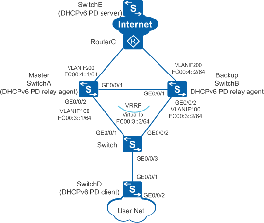
- In normal situations, hosts on the user network use SwitchA as the default gateway to access the Internet, and DHCPv6 prefix routing information on SwitchA can be backed up to SwitchB in real time or in batches.
- If SwitchA fails, SwitchB takes over services from SwitchA, ensuring uninterrupted network operation.
Precautions
This example describes only the configurations of DHCPv6 PD relay agents. For details about the DHCPv6 PD client and server configurations, see Example for Configuring the DHCPv6 PD Server and Client.
Ensure that there are reachable routes between the devices.
Configuration Roadmap
The configuration roadmap is as follows:
- Configure an IP address for each interface and configure a routing protocol to ensure network connectivity between devices.
- Configure a VRRP group on SwitchA and SwitchB. Configure a higher priority for SwitchA so that it becomes the master device to forward traffic. Configure a lower priority for SwitchB so that it becomes the backup device.
- Configure dual-node hot standby so that DHCPv6 prefix routing information on SwitchA can be backed up to SwitchB in real time or in batches through the backup link. This configuration ensures that services can be smoothly switched to the backup device if the master device fails.
Procedure
- Configure connectivity between devices.
# Configure an IP address for each interface. SwitchA is used as an example. The configuration of SwitchB is similar to that of SwitchA. For details, see the configuration files.
<HUAWEI> system-view
[HUAWEI] sysname SwitchA
[SwitchA] vlan batch 100 200
[SwitchA] ipv6
[SwitchA] interface gigabitethernet 0/0/2
[SwitchA-GigabitEthernet0/0/2] port link-type hybrid
[SwitchA-GigabitEthernet0/0/2] port hybrid pvid vlan 100
[SwitchA-GigabitEthernet0/0/2] port hybrid untagged vlan 100
[SwitchA-GigabitEthernet0/0/2] quit
[SwitchA] interface gigabitethernet 0/0/1
[SwitchA-GigabitEthernet0/0/1] port link-type hybrid
[SwitchA-GigabitEthernet0/0/1] port hybrid pvid vlan 200
[SwitchA-GigabitEthernet0/0/1] port hybrid untagged vlan 100 200
[SwitchA-GigabitEthernet0/0/1] quit
[SwitchA] interface vlanif 100
[SwitchA-Vlanif100] ipv6 enable
[SwitchA-Vlanif100] ipv6 address fc00:3::1/64
[SwitchA-Vlanif100] quit
[SwitchA] interface vlanif 200
[SwitchA-Vlanif200] ipv6 enable
[SwitchA-Vlanif200] ipv6 address fc00:4::1/64
[SwitchA-Vlanif200] quit
# Configure Layer 2 transparent transmission on the switch.
<HUAWEI> system-view
[HUAWEI] sysname Switch
[Switch] vlan 100
[Switch-vlan100] quit
[Switch] interface gigabitethernet 0/0/1
[Switch-GigabitEthernet0/0/1] port link-type hybrid
[Switch-GigabitEthernet0/0/1] port hybrid pvid vlan 100
[Switch-GigabitEthernet0/0/1] port hybrid untagged vlan 100
[Switch-GigabitEthernet0/0/1] quit
[Switch] interface gigabitethernet 0/0/2
[Switch-GigabitEthernet0/0/2] port link-type hybrid
[Switch-GigabitEthernet0/0/2] port hybrid pvid vlan 100
[Switch-GigabitEthernet0/0/2] port hybrid untagged vlan 100
[Switch-GigabitEthernet0/0/2] quit
- Configure the DHCPv6 PD relay function.
# Specify a DHCPv6 PD server IPv6 address FC00:5::1 on SwitchA. The configuration of SwitchB is similar to that of SwitchA. For details, see the configuration files.
[SwitchA] interface vlanif 100
[SwitchA-Vlanif100] dhcpv6 relay destination fc00:5::1
[SwitchA-Vlanif100] dhcpv6 relay advertise prefix-delegation route
[SwitchA-Vlanif100] quit
- Configure a VRRP group.
# Create VRRP group 1 and set the VRRP priority 120 on SwitchA.
[SwitchA] interface vlanif 100
[SwitchA-Vlanif100] vrrp6 vrid 1 virtual-ip fe80::1 link-local
[SwitchA-Vlanif100] vrrp6 vrid 1 virtual-ip fc00:3::3
[SwitchA-Vlanif100] vrrp6 vrid 1 priority 120
[SwitchA-Vlanif100] quit
# Create VRRP group 1 and set the VRRP priority 100 on .
[SwitchB] interface vlanif 100
[SwitchB-Vlanif100] vrrp6 vrid 1 virtual-ip fe80::1 link-local
[SwitchB-Vlanif100] vrrp6 vrid 1 virtual-ip fc00:3::3
[SwitchB-Vlanif100] quit
- Configure the dual-node hot standby function.
# Create HSB service 0 on SwitchA and configure IP addresses and port numbers for the active and standby channels.
[SwitchA] hsb-service 0
[SwitchA-hsb-service-0] service-ip-port local-ip fc00:4::1 peer-ip fc00:4::2 local-data-port 10241 peer-data-port 10241
[SwitchA-hsb-service-0] service-keep-alive detect retransmit 3 interval 6
[SwitchA-hsb-service-0] quit
# Create HSB service 0 on SwitchB and configure IP addresses and port numbers for the active and standby channels.
[SwitchB] hsb-service 0
[SwitchB-hsb-service-0] service-ip-port local-ip fc00:4::2 peer-ip fc00:4::1 local-data-port 10241 peer-data-port 10241
[SwitchB-hsb-service-0] service-keep-alive detect retransmit 3 interval 6
[SwitchB-hsb-service-0] quit
# Create HSB group 0 on SwitchA, and bind HSB group 0 to VRRP group 1. The configuration of SwitchB is similar to that of SwitchA. For details, see the configuration files.
[SwitchA] hsb-group 0
[SwitchA-hsb-group-0] bind-service 0
[SwitchA-hsb-group-0] track vrrp6 vrid 1 interface vlanif 100
# Bind the DHCPv6 service to the HSB group on SwitchA. The configuration of SwitchB is similar to that of SwitchA. For details, see the configuration files.
[SwitchA] hsb-service-type dhcp hsb-group 0# Enable HSB group 0 on SwitchA to make it take effect. The configuration of SwitchB is similar to that of SwitchA. For details, see the configuration files.
[SwitchA-hsb-group-0] hsb enable
[SwitchA-hsb-group-0] quit
- Verify the configuration.
# After the preceding configurations are complete, run the display vrrp command on SwitchA and SwitchB. The following command output shows that SwitchA is in Master state and SwitchB is in Backup state.
[SwitchA] display vrrp
  Vlanif100 | Virtual Router 1
    State        : Master
    Virtual IP     : FC00:3::3
    Master IP      : FC00:3::1
    PriorityRun    : 120
    PriorityConfig : 120
    MasterPriority : 120
    Preempt : YES   Delay Time : 0 s
    TimerRun : 1 s
    TimerConfig : 1 s
    Auth type : NONE
    Virtual MAC : 0000-5e00-0101
    Check TTL : YES
    Config type : normal-vrrp
    Backup-forward : disabled
    Create time : 2019-09-02 15:28:17
    Last change time : 0000-00-00 00:00:00
[SwitchB] display vrrp
  Vlanif100 | Virtual Router 1
    State        : Backup
    Virtual IP     : FC00:3::3
    Master IP      : FC00:3::1
    PriorityRun    : 100
    PriorityConfig : 100
    MasterPriority : 120
    Preempt : YES   Delay Time : 0 s
    TimerRun : 1 s
    TimerConfig : 1 s
    Auth type : NONE
    Virtual MAC : 0000-5e00-0101
    Check TTL : YES
    Config type : normal-vrrp
    Backup-forward : disabled
    Create time : 2019-09-02 15:28:17
    Last change time : 0000-00-00 00:00:00
# Run the display hsb-service service-index command on SwitchA and SwitchB to check the HSB service status. The following command output shows that the Service State field displays Connected, indicating that the active and standby channels have been established.
[SwitchA] display hsb-service 0
Hot Standby Service Information:
----------------------------------------------------------
  Local IP Address       : FC00:4::1
  Peer IP Address        : FC00:4::2
  Source Port            : 10241
  Destination Port       : 10241
  Keep Alive Times       : 5
  Keep Alive Interval    : 3
  Service State       : Connected
  Service Batch Modules  :
  Shared-key             : -
----------------------------------------------------------
[SwitchB] display hsb-service 0
Hot Standby Service Information:
----------------------------------------------------------
  Local IP Address       : FC00:4::2
  Peer IP Address        : FC00:4::1
  Source Port            : 10241
  Destination Port       : 10241
  Keep Alive Times       : 5
  Keep Alive Interval    : 3
  Service State       : Connected
  Service Batch Modules  :
  Shared-key             : -
----------------------------------------------------------
# Run the display hsb-group group-index command on SwitchA and SwitchB to check the HSB group status.
[SwitchA] display hsb-group 0
Hot Standby Group Information:
----------------------------------------------------------
  HSB-group ID                : 0
  Vrrp Group ID               : 1
  Vrrp Interface              : Vlanif100
  Service Index               : 0
  Group Vrrp Status           : Master
  Group Status                : Active
  Group Backup Process        : Realtime
  Peer Group Device Name      : SwitchB
  Peer Group Software Version : V200R019C10
  Group Backup Modules        : DHCP
[SwitchB] display hsb-group 0
Hot Standby Group Information:
----------------------------------------------------------
  HSB-group ID                : 0
  Vrrp Group ID               : 1
  Vrrp Interface              : Vlanif100
  Service Index               : 0
  Group Vrrp Status           : Backup
  Group Status                : Inactive
  Group Backup Process        : Realtime
  Peer Group Device Name      : SwitchA

  Peer Group Software Version : V200R019C10
  Group Backup Modules        : DHCP
# Run the shutdown command on GE0/0/2 and GE0/0/1 of SwitchA to simulate a fault on SwitchA.
[SwitchA] interface gigabitethernet 0/0/2
[SwitchA-GigabitEthernet0/0/2] shutdown
[SwitchA-GigabitEthernet0/0/2] quit
[SwitchA] interface gigabitethernet 0/0/1
[SwitchA-GigabitEthernet0/0/1] shutdown
[SwitchA-GigabitEthernet0/0/1] quit
# Run the display hsb-group group-index command on SwitchB to check the HSB group status. The following command output shows that SwitchB is in Master state.
[SwitchB] display hsb-group 0
Hot Standby Group Information:
----------------------------------------------------------
  HSB-group ID                : 0
  Vrrp Group ID               : 1
  Vrrp Interface              : Vlanif100
  Service Index               : 0
  Group Vrrp Status           : Master
  Group Status                : Independent
  Group Backup Process        : Independent
  Peer Group Device Name      : SwitchA
  Peer Group Software Version : V200R019C10
  Group Backup Modules        : DHCP
Configuration Files
SwitchA configuration file
# sysname SwitchA # ipv6 # vlan batch 100 200 # interface Vlanif100 ipv6 enable ipv6 address FC00:3::1/64 vrrp6 vrid 1 virtual-ip FE80::1 link-local vrrp6 vrid 1 virtual-ip FC00:3::3 vrrp6 vrid 1 priority 120 dhcpv6 relay destination FC00:5::1 dhcpv6 relay advertise prefix-delegation route # interface Vlanif200 ipv6 enable ipv6 address FC00:4::1/64 # interface GigabitEthernet0/0/1 port link-type hybrid port hybrid pvid vlan 200 port hybrid untagged vlan 100 200 # interface GigabitEthernet0/0/2 port link-type hybrid port hybrid pvid vlan 100 port hybrid untagged vlan 100 # hsb-service 0 service-ip-port local-ip FC00:4::1 peer-ip FC00:4::2 local-data-port 10241 peer-data-port 10241 service-keep-alive detect retransmit 3 interval 6 # hsb-group 0 track vrrp6 vrid 1 interface Vlanif100 bind-service 0 hsb enable # hsb-service-type dhcp hsb-group 0 # returnSwitchB configuration file
#
sysname SwitchB
#
ipv6
#
vlan batch 100 200
#
interface Vlanif100
 ipv6 enable
 ipv6 address FC00:3::2/64
 vrrp6 vrid 1 virtual-ip FE80::1 link-local
 vrrp6 vrid 1 virtual-ip FC00:3::3
 dhcpv6 relay destination FC00:5::1
 dhcpv6 relay advertise prefix-delegation route
#
interface Vlanif200
 ipv6 enable
 ipv6 address FC00:4::2/64
#
interface GigabitEthernet0/0/1
 port link-type hybrid
 port hybrid pvid vlan 200
 port hybrid untagged vlan 100 200
#
interface GigabitEthernet0/0/2
 port link-type hybrid
 port hybrid pvid vlan 100
 port hybrid untagged vlan 100
#
hsb-service 0
 service-ip-port local-ip FC00:4::2 peer-ip FC00:4::1 local-data-port 10241 peer-data-port 10241
 service-keep-alive detect retransmit 3 interval 6
#
hsb-group 0
 track vrrp6 vrid 1 interface Vlanif100
 bind-service 0
 hsb enable
#
hsb-service-type dhcp hsb-group 0
#
return
Switch configuration file
#
sysname Switch
#
vlan batch 100
#
interface GigabitEthernet0/0/1
 port link-type hybrid
 port hybrid pvid vlan 100
 port hybrid untagged vlan 100
#
interface GigabitEthernet0/0/2
 port link-type hybrid
 port hybrid pvid vlan 100
 port hybrid untagged vlan 100
#
return