Example for Configuring Basic IGMP Functions
Networking Requirements
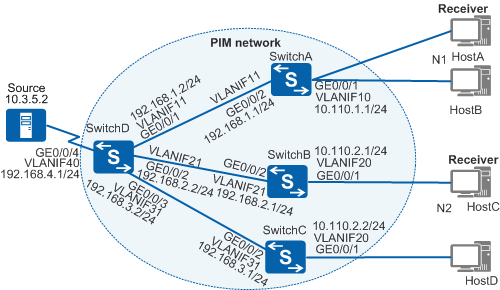
As shown in Figure 1, users are located on network segments N1 and N2. On the PIM network, SwitchA connects to network segment N1, whereas SwitchB and SwitchC connect to network segment N2. The PIM network uses multicast addresses 225.1.1.1 through 225.1.1.5 to transmit video streams.
HostA on N1 and HostC on N2 want to receive video streams in multicast mode. HostA only subscribes to programs of group 225.1.1.1, and HostC subscribes to programs of all groups. You need to configure the switches to allow HostA to receive only video streams of group 225.1.1.1 while allowing HostC to receive video streams of all groups.

In this scenario, to avoid loops, ensure that all connected interfaces have STP disabled and connected interfaces are removed from VLAN 1. If STP is enabled and VLANIF interfaces of switches are used to construct a Layer 3 ring network, an interface on the network will be blocked. As a result, Layer 3 services on the network cannot run normally.
Configuration Roadmap
To meet the preceding requirements, configure basic IGMP functions on the switches, and configure a group policy on SwitchA to limit the multicast group range on the interface connected to network segment N1. The configuration roadmap is as follows:
- To ensure that data sent from multicast sources can be correctly forwarded to the user network segments, configure a unicast routing protocol on the network to implement IP interworking. Multicast routing protocols are dependent on unicast routing protocols.
- To enable the switches to forward video streams to the hosts in multicast mode, configure basic multicast functions on the switches.
- To allow HostA to receive only multicast data sent to multicast group 225.1.1.1, configure a group policy on SwitchA's interface connected to N1 to filter multicast data sent to this network segment.
Procedure
- Configure IP addresses for interfaces and configure a unicast routing protocol on each switch.
# Configure IP addresses and masks for switch interfaces according to Figure 1. Configure OSPF on the switches to implement IP interworking and dynamic route update. The configurations of SwitchB, SwitchC, and SwitchD are similar to the configuration of SwitchA, and are not mentioned here. See Configuration Files.
<HUAWEI> system-view
[HUAWEI] sysname SwitchA
[SwitchA] vlan batch 10 11
[SwitchA] interface gigabitethernet 0/0/1
[SwitchA-GigabitEthernet0/0/1] port link-type hybrid
[SwitchA-GigabitEthernet0/0/1] port hybrid untagged vlan 10
[SwitchA-GigabitEthernet0/0/1] port hybrid pvid vlan 10
[SwitchA-GigabitEthernet0/0/1] quit
[SwitchA] interface gigabitethernet 0/0/2
[SwitchA-GigabitEthernet0/0/2] port link-type trunk
[SwitchA-GigabitEthernet0/0/2] port trunk allow-pass vlan 11
[SwitchA-GigabitEthernet0/0/2] quit
[SwitchA] interface vlanif 10
[SwitchA-Vlanif10] ip address 10.110.1.1 24
[SwitchA-Vlanif10] quit
[SwitchA] interface vlanif 11
[SwitchA-Vlanif11] ip address 192.168.1.1 24
[SwitchA-Vlanif11] quit
[SwitchA] ospf
[SwitchA-ospf-1] area 0
[SwitchA-ospf-1-area-0.0.0.0] network 10.110.1.0 0.0.0.255
[SwitchA-ospf-1-area-0.0.0.0] network 192.168.1.0 0.0.0.255
[SwitchA-ospf-1-area-0.0.0.0] quit
[SwitchA-ospf-1] quit
- Enable multicast routing on the switches and enable Protocol Independent Multicast - Sparse Mode (PIM-SM) on all interfaces.
# Enable IP multicast routing on SwitchA and enable PIM-SM on all its interfaces. The configurations of SwitchB, SwitchC, and SwitchD are similar to the configuration of SwitchA, and are not mentioned here. See Configuration Files.
[SwitchA] multicast routing-enable
[SwitchA] interface vlanif 10
[SwitchA-Vlanif10] pim sm
[SwitchA-Vlanif10] quit
[SwitchA] interface vlanif 11
[SwitchA-Vlanif11] pim sm
[SwitchA-Vlanif11] quit
- Configure a static rendezvous point (RP).
# Configure a static RP on SwitchA. Specify VLANIF40 of SwitchD as a static RP. The configurations of SwitchB, SwitchC, and SwitchD are similar to the configuration of SwitchA, and are not mentioned here. See Configuration Files.
[SwitchA] pim
[SwitchA-pim] static-rp 192.168.4.1
[SwitchA-pim] quit
- On SwitchA, SwitchB, and SwitchC, enable IGMP on the interfaces connected to the user network segments.
# Enable IGMP on VLANIF10 of SwitchA. The configurations of SwitchB and SwitchC are similar to the configuration of SwitchA, and are not mentioned here. See Configuration Files.
[SwitchA] interface vlanif 10
[SwitchA-Vlanif10] igmp enable
[SwitchA-Vlanif10] quit
- Allow VLANIF10 of SwitchA to join only multicast group 225.1.1.1.
# On SwitchA, create an ACL, configure a rule that only permits packets of the multicast group 225.1.1.1, and apply the ACL rule to VLANIF10.
[SwitchA] acl number 2001
[SwitchA-acl-basic-2001] rule permit source 225.1.1.1 0
[SwitchA-acl-basic-2001] quit
[SwitchA] interface vlanif 10
[SwitchA-Vlanif10] igmp group-policy 2001
[SwitchA-Vlanif10] quit
- Verify the configuration.
# Run the display igmp interface command to check the IGMP configuration and running status on each interface. The IGMP command output on VLANIF10 of SwitchA is as follows:
[SwitchA] display igmp interface vlanif 10
Interface information of VPN-Instance: public net
 Vlanif10(10.110.1.1):
  IGMP is enabled
  Current IGMP version is 2
  IGMP state: up
  IGMP group policy: 2001
  IGMP limit: -
  Value of query interval for IGMP (negotiated): -
  Value of query interval for IGMP (configured): 60 s
  Value of other querier timeout for IGMP: 0 s
  Value of maximum query response time for IGMP: 10 s
  Querier for IGMP: 10.110.1.1 (this router)
 Total 1 IGMP Group reported
The preceding information shows that IGMP is enabled on VLANIF10 of SwitchA, and a group policy referencing ACL 2001 has been applied to this interface.
# Run the display pim routing-table command to check the PIM-SM multicast routing table on each switch.
The PIM-SM multicast routing table on SwitchB is as follows:
[SwitchB] display pim routing-table
 VPN-Instance: public net
 Total 2 (*, G) entries; 2 (S, G) entries

 (*, 225.1.1.1)
     RP: 192.168.4.1
     Protocol: pim-sm, Flag: WC
     UpTime: 00:21:35
     Upstream interface: Vlanif21
         Upstream neighbor: 192.168.2.2
         RPF prime neighbor: 192.168.2.2
     Downstream interface(s) information:
     Total number of downstreams: 1
         1: Vlanif20
             Protocol: igmp, UpTime: 00:21:35, Expires: -

 (10.3.5.2, 225.1.1.1)
     RP: 192.168.4.1
     Protocol: pim-sm, Flag: SPT ACT
     UpTime: 00:42:46
     Upstream interface: Vlanif21
         Upstream neighbor: 192.168.2.2
         RPF prime neighbor: 192.168.2.2
     Downstream interface(s) information:
     Total number of downstreams: 1
         1: Vlanif20
             Protocol: pim-sm, UpTime: 00:21:35, Expires: -

 (*, 225.1.1.2)
     RP: 192.168.4.1
     Protocol: pim-sm, Flag: WC
     UpTime: 00:06:02
     Upstream interface: Vlanif21
         Upstream neighbor: 192.168.2.2
         RPF prime neighbor: 192.168.2.2
     Downstream interface(s) information:
     Total number of downstreams: 1
         1: Vlanif20
             Protocol: igmp, UpTime: 00:06:02, Expires: -

 (10.3.5.2, 225.1.1.2)
     RP: 192.168.4.1
     Protocol: pim-sm, Flag: SPT ACT
     UpTime: 00:15:12
     Upstream interface: Vlanif21
         Upstream neighbor: 192.168.2.2
         RPF prime neighbor: 192.168.2.2
     Downstream interface(s) information:
     Total number of downstreams: 1
         1: Vlanif20
             Protocol: pim-sm, UpTime: 00:06:04, Expires: -
The command output shows that (*, 225.1.1.1), (10.3.5.2, 225.1.1.1), (*, 225.1.1.2), and (10.3.5.2, 225.1.1.2) entries exist on RouterB. This indicates that VLANIF20 has joined multicast groups 225.1.1.1 and 225.1.1.2 and can receive multicast data from multicast source 10.3.5.2.
The PIM-SM multicast routing table on SwitchA is as follows:
[SwitchA] display pim routing-table
 VPN-Instance: public net
 Total 1 (*, G) entry; 1 (S, G) entry

 (*, 225.1.1.1)
     RP: 192.168.4.1
     Protocol: pim-sm, Flag: WC
     UpTime: 00:21:35
     Upstream interface: Vlanif11
         Upstream neighbor: 192.168.1.2
         RPF prime neighbor: 192.168.1.2
     Downstream interface(s) information:
     Total number of downstreams: 1
         1: Vlanif10
             Protocol: igmp, UpTime: 00:21:35, Expires: -

 (10.3.5.2, 225.1.1.1)
     RP: 192.168.4.1
     Protocol: pim-sm, Flag: SPT ACT
     UpTime: 00:42:46
     Upstream interface: Vlanif11
         Upstream neighbor: 192.168.1.2
         RPF prime neighbor: 192.168.1.2
     Downstream interface(s) information:
     Total number of downstreams: 1
         1: Vlanif10
             Protocol: pim-sm, UpTime: 00:21:35, Expires: -
The command output shows that (*, 225.1.1.1) and (10.3.5.2, 225.1.1.1) entries exist on SwitchA. This is because an ACL is configured on VLANIF10 of SwitchA.
Configuration Files
SwitchA configuration file
#
sysname SwitchA
#
vlan batch 10 to 11
#
multicast routing-enable
#
acl number 2001
 rule 5 permit source 225.1.1.1 0
#
interface Vlanif10
 ip address 10.110.1.1 255.255.255.0
 pim sm
 igmp enable
 igmp group-policy 2001
#
interface Vlanif11
 ip address 192.168.1.1 255.255.255.0
 pim sm
#
interface GigabitEthernet0/0/1
 port link-type hybrid
 port hybrid pvid vlan 10
 port hybrid untagged vlan 10
#
interface GigabitEthernet0/0/2
 port link-type trunk
 port trunk allow-pass vlan 11
#
ospf 1
 area 0.0.0.0
  network 10.110.1.0 0.0.0.255
  network 192.168.1.0 0.0.0.255
#
pim
 static-rp 192.168.4.1
#
return
SwitchB configuration file
#
sysname SwitchB
#
vlan batch 20 to 21
#
multicast routing-enable
#
interface Vlanif20
 ip address 10.110.2.1 255.255.255.0
 pim sm
 igmp enable
#
interface Vlanif21
 ip address 192.168.2.1 255.255.255.0
 pim sm
#
interface GigabitEthernet0/0/1
 port link-type hybrid
 port hybrid pvid vlan 20
 port hybrid untagged vlan 20
#
interface GigabitEthernet0/0/2
 port link-type trunk
 port trunk allow-pass vlan 21
#
ospf 1
 area 0.0.0.0
  network 10.110.2.0 0.0.0.255
  network 192.168.2.0 0.0.0.255
#
pim
 static-rp 192.168.4.1
#
return
SwitchC configuration file
#
sysname SwitchC
#
vlan batch 20 31
#
multicast routing-enable
#
interface Vlanif20
 ip address 10.110.2.2 255.255.255.0
 pim sm
 igmp enable
#
interface Vlanif31
 ip address 192.168.3.1 255.255.255.0
 pim sm
#
interface GigabitEthernet0/0/1
 port link-type hybrid
 port hybrid pvid vlan 20
 port hybrid untagged vlan 20
#
interface GigabitEthernet0/0/2
 port link-type trunk
 port trunk allow-pass vlan 31
#
ospf 1
 area 0.0.0.0
  network 10.110.2.0 0.0.0.255
  network 192.168.3.0 0.0.0.255
#
pim
 static-rp 192.168.4.1
#
return
SwitchD configuration file
#
sysname SwitchD
#
vlan batch 11 21 31 40
#
multicast routing-enable
#
interface Vlanif11
 ip address 192.168.1.2 255.255.255.0
 pim sm
#
interface Vlanif21
 ip address 192.168.2.2 255.255.255.0
 pim sm
#
interface Vlanif31
 ip address 192.168.3.2 255.255.255.0
 pim sm
#
interface Vlanif40
 ip address 192.168.4.1 255.255.255.0
 pim sm
#
interface GigabitEthernet0/0/1
 port link-type trunk
 port trunk allow-pass vlan 11
#
interface GigabitEthernet0/0/2
 port link-type trunk
 port trunk allow-pass vlan 21
#
interface GigabitEthernet0/0/3
 port link-type trunk
 port trunk allow-pass vlan 31
#
interface GigabitEthernet0/0/4
 port link-type trunk
 port trunk allow-pass vlan 40
#
ospf 1
 area 0.0.0.0
  network 192.168.1.0 0.0.0.255
  network 192.168.2.0 0.0.0.255
  network 192.168.3.0 0.0.0.255
  network 192.168.4.0 0.0.0.255
#
pim
 static-rp 192.168.4.1
#
return