Example for Configuring IP FRR on the Public Network
Networking Requirements
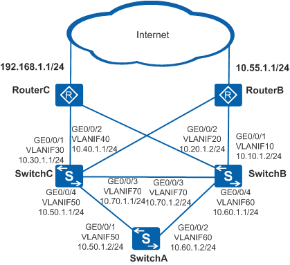
In Figure 1, RouterB and RouterC are egress routers on the Internet. SwitchA is connected to two core switches SwitchB and SwitchC through two GE interfaces. Each of SwitchB and SwitchC is connected to the two egress routers through two GE interfaces. When a fault occurs on the link between SwitchB and RouterB, SwitchB must rapidly respond to the link fault and use a backup route for data forwarding to ensure that services are forwarded correctly.

In this scenario, ensure that all connected interfaces have STP disabled. If STP is enabled and VLANIF interfaces of switches are used to construct a Layer 3 ring network, an interface on the network will be blocked. As a result, Layer 3 services on the network cannot run normally.
Configuration Roadmap
The configuration roadmap is as follows:
Configure static routes on SwitchA to ensure that packets destined for 192.168.1.1/24 are forwarded by SwitchC and packets destined for 10.55.1.1/24 are forwarded by SwitchB.
Configure a route-policy on SwitchB and apply this route-policy for IP FRR on the public network so that services can be rapidly switched to the backup link SwitchB→SwitchC→RouterB when the primary link SwitchB→RouterB fails.
Procedure
- Create VLANs and add interfaces to the VLANs.
# Configure SwitchA. The configurations of SwitchB and SwitchC are similar to the configuration of SwitchA.
<HUAWEI> system-view
[HUAWEI] sysname SwitchA
[SwitchA] vlan batch 50 60
[SwitchA] interface gigabitethernet 0/0/1
[SwitchA-GigabitEthernet0/0/1] port link-type trunk
[SwitchA-GigabitEthernet0/0/1] port trunk allow-pass vlan 50
[SwitchA-GigabitEthernet0/0/1] quit
[SwitchA] interface gigabitethernet 0/0/2
[SwitchA-GigabitEthernet0/0/2] port link-type trunk
[SwitchA-GigabitEthernet0/0/2] port trunk allow-pass vlan 60
[SwitchA-GigabitEthernet0/0/2] quit
- Assign IPv4 addresses to VLANIF interfaces.
# Configure SwitchA. The configurations of SwitchB and SwitchC are similar to the configuration of SwitchA.
[SwitchA] interface vlanif 50
[SwitchA-Vlanif50] ip address 10.50.1.2 24
[SwitchA-Vlanif50] quit
[SwitchA] interface vlanif 60
[SwitchA-Vlanif60] ip address 10.60.1.2 24
[SwitchA-Vlanif60] quit
- Configure basic OSPF functions on SwitchB and SwitchC.
# Configure SwitchB.
[SwitchB] ospf
[SwitchB-ospf-1] area 0
[SwitchB-ospf-1-area-0.0.0.0] network 10.10.1.0 0.0.0.255
[SwitchB-ospf-1-area-0.0.0.0] network 10.20.1.0 0.0.0.255
[SwitchB-ospf-1-area-0.0.0.0] network 10.60.1.0 0.0.0.255
[SwitchB-ospf-1-area-0.0.0.0] network 10.70.1.0 0.0.0.255
[SwitchB-ospf-1-area-0.0.0.0] quit
[SwitchB-ospf-1] quit
# Configure SwitchC.
[SwitchC] ospf
[SwitchC-ospf-1] area 0
[SwitchC-ospf-1-area-0.0.0.0] network 10.30.1.0 0.0.0.255
[SwitchC-ospf-1-area-0.0.0.0] network 10.40.1.0 0.0.0.255
[SwitchC-ospf-1-area-0.0.0.0] network 10.50.1.0 0.0.0.255
[SwitchC-ospf-1-area-0.0.0.0] network 10.70.1.0 0.0.0.255
[SwitchC-ospf-1-area-0.0.0.0] quit
[SwitchC-ospf-1] quit
- Configure IPv4 addresses and basic OSPF functions on RouterB and RouterC to ensure that there are reachable routes between RouterB, RouterC, SwitchB, and SwitchC.
- Configure static routes on SwitchA to ensure that packets
destined for 192.168.1.1/24 are forwarded by SwitchC and packets destined for
10.55.1.1/24 are forwarded by SwitchB.
# Configure SwitchA.
[SwitchA] ip route-static 10.55.1.0 24 vlanif 60 10.60.1.1
[SwitchA] ip route-static 192.168.1.0 24 vlanif 50 10.50.1.1
- Configure a route-policy and enable IP FRR on the public
network.
# Configure an IP prefix list on SwitchB.
[SwitchB] ip ip-prefix ip_frr_pre index 10 permit 10.55.1.0 24# On SwitchB, configure a route-policy, backup next hop, and backup outbound interface.
[SwitchB] route-policy ip_frr_rp permit node 10
[SwitchB-route-policy] if-match ip-prefix ip_frr_pre
[SwitchB-route-policy] apply backup-nexthop 10.70.1.1
[SwitchB-route-policy] apply backup-interface vlanif 70
[SwitchB-route-policy] quit
# On SwitchB, enable IP FRR on the public network.
[SwitchB] ip frr route-policy ip_frr_rp - Check information about the backup outbound interface and
backup next hop.
# Check information about the backup outbound interface and backup next hop on SwitchB.
[SwitchB] display ip routing-table verbose
Route Flags: R - relay, D - download to fib, T - to vpn-instance
------------------------------------------------------------------------------
Routing Tables: Public
         Destinations : 1       Routes : 1

Destination: 10.55.1.0/24
     Protocol: OSPF                    Process ID: 1
   Preference: 10                            Cost: 2
      NextHop: 10.10.1.1                Neighbour: 0.0.0.0
        State: Active Adv                     Age: 1d17h58m22s
          Tag: 0                         Priority: medium
        Label: NULL                       QoSInfo: 0x0
   IndirectID: 0x80000001
  RelayNextHop: 0.0.0.0                 Interface:  Vlanif10
      TunnelID: 0x0                         Flags: RD
   BkNextHop: 10.70.1.1             BkInterface: Vlanif70
       BkLabel: NULL                  SecTunnelID: 0x0
  BkPETunnelID: 0x0               BkPESecTunnelID: 0x0
  BkIndirectID: 0x0
Configuration Files
SwitchA configuration file
#
sysname SwitchA
#
vlan batch 50 60
#
interface Vlanif50
 ip address 10.50.1.2 255.255.255.0
#
interface Vlanif60
 ip address 10.60.1.2 255.255.255.0
#
interface GigabitEthernet0/0/1
 port link-type trunk
 port trunk allow-pass vlan 50
#
interface GigabitEthernet0/0/2
 port link-type trunk
 port trunk allow-pass vlan 60
#
ip route-static 10.55.1.0 255.255.255.0 Vlanif60 10.60.1.1
ip route-static 192.168.1.0 255.255.255.0 Vlanif50 10.50.1.1
#
return
SwitchB configuration file
#
sysname SwitchB
#
vlan batch 10 20 60 70
#
ip frr route-policy ip_frr_rp
#
interface Vlanif10
 ip address 10.10.1.2 255.255.255.0
#
interface Vlanif20
 ip address 10.20.1.2 255.255.255.0
#
interface Vlanif60
 ip address 10.60.1.1 255.255.255.0
#
interface Vlanif70
 ip address 10.70.1.2 255.255.255.0
#
interface GigabitEthernet0/0/1
 port link-type trunk
 port trunk allow-pass vlan 10
#
interface GigabitEthernet0/0/2
 port link-type trunk
 port trunk allow-pass vlan 20
#
interface GigabitEthernet0/0/3
 port link-type trunk
 port trunk allow-pass vlan 70
#
interface GigabitEthernet0/0/4
 port link-type trunk
 port trunk allow-pass vlan 60
#
ospf 1
 area 0.0.0.0
  network 10.10.1.0 0.0.0.255
  network 10.20.1.0 0.0.0.255
  network 10.60.1.0 0.0.0.255
  network 10.70.1.0 0.0.0.255
#
ip ip-prefix ip_frr_pre index 10 permit 10.55.1.0 24
#
route-policy ip_frr_rp permit node 10
 if-match ip-prefix ip_frr_pre
 apply backup-nexthop 10.70.1.1
 apply backup-interface Vlanif70
#
return
SwitchC configuration file
#
sysname SwitchC
#
vlan batch 30 40 50 70
#
interface Vlanif30
 ip address 10.30.1.1 255.255.255.0
#
interface Vlanif40
 ip address 10.40.1.1 255.255.255.0
#
interface Vlanif50
 ip address 10.50.1.1 255.255.255.0
#
interface Vlanif70
 ip address 10.70.1.1 255.255.255.0
#
interface GigabitEthernet0/0/1
 port link-type trunk
 port trunk allow-pass vlan 30
#
interface GigabitEthernet0/0/2
 port link-type trunk
 port trunk allow-pass vlan 40
#
interface GigabitEthernet0/0/3
 port link-type trunk
 port trunk allow-pass vlan 70
#
interface GigabitEthernet0/0/4
 port link-type trunk
 port trunk allow-pass vlan 50
#
ospf 1
 area 0.0.0.0
  network 10.30.1.0 0.0.0.255
  network 10.40.1.0 0.0.0.255
  network 10.50.1.0 0.0.0.255
  network 10.70.1.0 0.0.0.255
#
return