Example for Configuring IPSG Based on a DHCP Snooping Dynamic Binding Table to Prevent Hosts from Changing Their Own IP Addresses
Networking Requirements
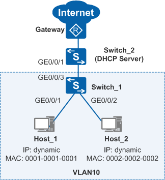
In Figure 1, hosts access the Internet through Switch_1, and Switch_2 functions as a DHCP server to allocate IP addresses to the hosts. The gateway is the egress device of the enterprise network. The administrator requires that the hosts use dynamically allocated IP addresses. The hosts cannot change their IP addresses to statically configured IP addresses to access the Internet.
Configuration Roadmap
The requirements can be met by configuring IPSG. The configuration roadmap is as follows:
- Configure the DHCP server (IP address pool 10.1.1.0/24) on Switch_2 to allocate IP addresses to hosts.
- Configure DHCP snooping on Switch_1. Hosts can then obtain IP addresses from the valid DHCP server, and the DHCP server can generate DHCP snooping dynamic binding entries. These entries record the bindings of IP addresses, MAC addresses, VLANs, and interfaces of hosts.
- Enable IPSG in the VLAN to which the hosts belong on Switch_1 to prevent the hosts from accessing the Internet with changed IP addresses.
Procedure
- Configure the DHCP server on Switch_2.
<HUAWEI> system-view
[HUAWEI] sysname Switch_2
[Switch_2] vlan batch 10
[Switch_2] interface gigabitethernet 0/0/1
[Switch_2-GigabitEthernet0/0/1] port link-type trunk
[Switch_2-GigabitEthernet0/0/1] port trunk allow-pass vlan 10
[Switch_2-GigabitEthernet0/0/1] quit
[Switch_2] dhcp enable
[Switch_2] ip pool 10
[Switch_2-ip-pool-10] network 10.1.1.0 mask 24
[Switch_2-ip-pool-10] gateway-list 10.1.1.1
[Switch_2-ip-pool-10] quit
[Switch_2] interface vlanif 10
[Switch_2-Vlanif10] ip address 10.1.1.1 255.255.255.0
[Switch_2-Vlanif10] dhcp select global
[Switch_2-Vlanif10] quit
- Configure DHCP snooping on Switch_1.
# Specify the VLAN to which the interfaces belong.
<HUAWEI> system-view
[HUAWEI] sysname Switch_1
[Switch_1] vlan batch 10
[Switch_1] interface gigabitethernet 0/0/1
[Switch_1-GigabitEthernet0/0/1] port link-type access
[Switch_1-GigabitEthernet0/0/1] port default vlan 10
[Switch_1-GigabitEthernet0/0/1] quit
[Switch_1] interface gigabitethernet 0/0/2
[Switch_1-GigabitEthernet0/0/2] port link-type access
[Switch_1-GigabitEthernet0/0/2] port default vlan 10
[Switch_1-GigabitEthernet0/0/2] quit
[Switch_1] interface gigabitethernet 0/0/3
[Switch_1-GigabitEthernet0/0/3] port link-type trunk
[Switch_1-GigabitEthernet0/0/3] port trunk allow-pass vlan 10
[Switch_1-GigabitEthernet0/0/3] quit
# Enable DHCP snooping and configure GE0/0/3 connected to the DHCP server as a trusted interface.
[Switch_1] dhcp enable
[Switch_1] dhcp snooping enable
[Switch_1] vlan 10
[Switch_1-vlan10] dhcp snooping enable
[Switch_1-vlan10] dhcp snooping trusted interface gigabitethernet 0/0/3
- Enable IPSG in VLAN 10 on Switch_1.
[Switch_1-vlan10] ip source check user-bind enable
[Switch_1-vlan10] quit
- Verify the configuration.
After the hosts go online, run the display dhcp snooping user-bind all command on Switch_1 to view dynamic binding entries of the hosts.
[Switch_1] display dhcp snooping user-bind all
DHCP Dynamic Bind-table:
Flags:O - outer vlan ,I - inner vlan ,P - Vlan-mapping
IP Address       MAC Address     VSI/VLAN(O/I/P) Interface      Lease
--------------------------------------------------------------------------------
10.1.1.254       0001-0001-0001  --  /10  /--    GE0/0/1        2014.08.17-07:31
10.1.1.253       0002-0002-0002  --  /10  /--    GE0/0/2        2014.08.17-07:34
--------------------------------------------------------------------------------
print count:      2     total count:      2
The hosts can access the Internet using the IP addresses dynamically allocated by the DHCP server. After the hosts change their dynamic IP addresses to different statically configured IP addresses, the hosts cannot access the Internet.
Configuration Files
Switch_1 configuration file
#
sysname Switch_1
#
vlan batch 10
#
dhcp enable
#
dhcp snooping enable
#
vlan 10
 dhcp snooping enable
 dhcp snooping trusted interface GigabitEthernet0/0/3
 ipv4 source check user-bind enable
 ipv6 source check user-bind enable
#
interface GigabitEthernet0/0/1
 port link-type access
 port default vlan 10
#
interface GigabitEthernet0/0/2
 port link-type access
 port default vlan 10
#
interface GigabitEthernet0/0/3
 port link-type trunk
 port trunk allow-pass vlan 10
#
return
Switch_2 configuration file
#
sysname Switch_2
#
vlan batch 10
#
dhcp enable
#
ip pool 10
 gateway-list 10.1.1.1
 network 10.1.1.0 mask 255.255.255.0
#
interface Vlanif10
 ip address 10.1.1.1 255.255.255.0
 dhcp select global
#
interface GigabitEthernet0/0/1
 port link-type trunk
 port trunk allow-pass vlan 10
#
return