Installing Stack Cables and Powering On the Switch
Preparing for Installation
Ensure that the following components and tools are available before the installation:
- Components: copper cables, optical modules and fibers, or active optical cables (AOCs) (For the stack cables applicable to different devices, see Stack Support and Version Requirements.)
- Tools: ESD wrist strap or ESD gloves
Precautions

When installing or removing optical fibers, do not look into optical ports or connectors without eye protection.
- Wear an ESD wrist strap or ESD gloves during the installation.
- Prevent the cables or optical fibers from being twisted.
- Install or remove optical fibers carefully to avoid damages to fiber connectors.
- The bend radius of optical fibers or cables must be larger than the minimum bend radius. The minimum bend radius of SFP+ cables is 25 mm; the minimum bend radius of AOC cables is 30 mm; the bend radius of optical fibers is generally greater than or equal to 40 mm.
- If the fiber connector is dirty, use an alcohol swab or a piece of air-laid paper to gently wipe the fiber connector in one direction.
- To remove a cable, gently push the connector of the cable and then pull out the cable by the pull ring.
Installation Procedure
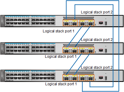
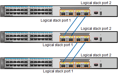
Stack member switches can form a chain or ring topology through service port connections. Figure 1 and Figure 2 shows stack cable connections in a stack that is set up by three S5720-28X-LI-AC switches. On the member switches, the first two 10GE optical ports are configured as stack member ports of logical stack port 1, and the last 10GE optical ports are configured as stack member ports of logical stack port 2.

- Power off the switch before connecting stack cables.
- Stack member ports of a logical stack port (stack-port n/1) on one switch must be connected to stack member ports of a logical stack port (stack-port m/2) on another switch.
- Multiple stack member ports can be bundled into a logical stack port to improve stack reliability and bandwidth. The stack will not split as long as one physical link is available between the member switches.
- If the logical stack ports on two ends (stack-port n/1 on one switch and stack-port m/2 on the other) both contain multiple stack member ports, the stack member ports can be connected in any sequence.
- If there are more than two member switches, use the ring topology to improve system reliability. The stack bandwidth is the minimum bandwidth among all stack ports.
- If there are only two member switches, you are advised to create only one logical stack port on each member switch. The logical stack port can contain multiple stack member ports.
To ensure that a stack can be set up successfully, you are advised to perform operations in the following sequence (in a chain topology with three switches A, B, and C):
- Wear an ESD wrist strap and connect the other end of the strap to the ESD jack on the cabinet.
- Use stack cables to connect SwitchA and SwitchB.
- Power on SwitchA and then SwitchB.
- Check whether SwitchA and SwitchB have set up a stack successfully. (See Checking Whether a Stack Has Been Established Through Service Port Connections.)
- Use stack cables to connect SwitchC and SwitchB, and then power on SwitchC.
- Check whether SwitchA, SwitchB, and SwitchC have set up a stack successfully. (See Checking Whether a Stack Has Been Established Through Service Port Connections.)
To specify a member switch as the master switch, power on that switch first. Power on the other member switches after that switch has started. In this example, SwitchA becomes the master switch after the stack is set up.