Establishing a Stack Using Dedicated Stack Cables
Installation Preparation
- Components: dedicated stack cables
- Tools: ESD wrist strap or ESD gloves
Precautions
- Wear an ESD wrist strap or ESD gloves during the installation.
- Ensure that the stack cables are not tangled with other cables.
- To remove a cable, gently push the connector of the cable and then pull out the cable by the pull ring.
Cable Connections
- Logical stack port 1 on one switch must be connected to logical stack port 2 on another switch. Logical stack port numbers have been preconfigured for physical ports as shown in Table 1. To view the port numbers, run the display stack port auto-cable-info command.
Table 1 Preconfigured logical stack port numbers Ports Supporting Dedicated Stack Cables
Logical Stack Port 1
Logical Stack Port 2
Two uplink optical ports (non-combo ports) on the front panel
Uplink optical port 1
Uplink optical port 2
Four uplink optical ports on the front panel
First two uplink optical ports
Last two uplink optical ports
Eight uplink optical ports on the front panel
Uplink optical ports 1, 2, 5, and 6
Uplink optical ports 3, 4, 7, and 8
Eight optical ports on the S7X08000 card (8 x 10GE mode) of the S5732-H24UM2CC or S5732-H48UM2CC
Optical ports 1, 2, 5, and 6
Optical ports 3, 4, 7, and 8
All 16 optical ports on the front panel
Optical ports 1, 2, 5, 6, 9, 10, 13, and 14
Optical ports 3, 4, 7, 8, 11, 12, 15, and 16
Last 16 optical ports among all 24 optical ports on the front panel
Optical ports 9, 10, 13, 14, 17, 18, 21, and 22
Optical ports 11, 12, 15, 16, 19, 20, 23, and 24
Last 16 optical ports among all 32 optical ports on the front panel
Optical ports 17, 18, 21, 22, 25, 26, 29, and 30
Optical ports 19, 20, 23, 24, 27, 28, 31, and 32
Last 16 optical ports among all 48 optical ports on the front panel
Optical ports 33, 34, 37, 38, 41, 42, 45, and 46
Optical ports 35, 36, 39, 40, 43, 44, 47, and 48
- Stack member ports of a logical stack port can be connected at any sequence. Each logical stack port can have one or more physical ports connected.
- If logical stack port numbers have been configured manually, these port numbers will not change after stack cables are connected. The preconfigured logical stack port numbers do not take effect. Connect stack cables according to the configured port numbers.
- In unconfigured deployment scenarios, you are advised to connect member switches based on the following rules:
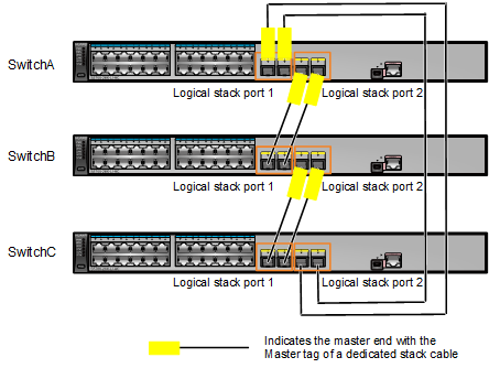
- Connect the switches in sequence from top to bottom, as shown in Figure 1.
- Ensure that all logical stack ports of the top switch are connected to the master ends of cables, all logical stack ports of the bottom switch are connected to the slave ends of cables, and two logical stack ports of the intermediate switch are connected to the master and slave ends respectively.
- After the switches have been connected using dedicated stack cables, they automatically set up a stack and their stack IDs as well as stack roles are automatically assigned.
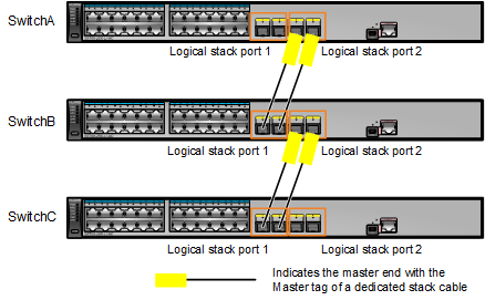
- If the switches are not connected in a ring topology, you only need to ensure that logical stack port 1 of the local switch is connected to logical stack port 2 of the remote switch. In this situation, these switches can set up a stack, but their master and standby roles and stack IDs are randomly generated.
- To perform stack capacity expansion on a switch that already has the configuration, pay attention to the following:
- Ports with dedicated stack cables installed cannot have any service configuration.
- You only need to ensure that logical stack port 1 of one switch is connected to logical stack port 2 of another switch, without having to consider the master/slave ends of dedicated stack cables.
- The existing stack ID of the switch is used when no stack ID conflict occurs. If such a conflict occurs, a new stack ID is automatically assigned to the switch.
Installation Procedure
Stack member switches can set up a stack in a chain or ring topology through service port connections. Figure 1 and Figure 2 show stack cable connections in a stack that is set up by three S5720-28X-LI-AC switches in ring and chain topologies respectively. On these member switches, the first two 10GE optical ports are preconfigured as stack member ports of logical stack port 1, and the last two 10GE optical ports are preconfigured as stack member ports of logical stack port 2. Here, each logical stack port has two stack member ports connected and can also have one stack member port connected. To ensure reliability, it is recommended that a logical stack port have two or more stack member ports connected.

- Before using dedicated stack cables to connect member switches, you are advised to power off all member switches to ensure safety.
- The two ends of a dedicated stack cable are the master end with the Master tag and the standby end without any tag.
- When the switch is running and a dedicated stack cable is removed and inserted to a port, this port changes between a service port and a stack port after 60 seconds to prevent flapping in the event that this cable is removed and inserted to this port multiple times in a short time. That is, this port becomes a stack port 60 seconds after a dedicated stack cable is inserted to it or it becomes a service port 60 seconds after this cable is removed from it. If the stack configuration has been saved before the dedicated stack cable is removed from a stack port, this stack port will not automatically become a service port.
- If ports cannot automatically become stack ports after they have dedicated stack cables connected, an alarm 1.3.6.1.4.1.2011.5.25.183.1.22.64 hwStackAutoConfigFailed is generated. Solve this problem based on the possible causes and procedure described in this alarm.
- If the switches have been powered off before they have stack cables connected, you are advised to power on them in sequence. If you want a specific switch to become the master switch, power on it first. After it starts, power on other switches. In the following example, three switches, SwitchA, SwitchB, and SwitchC set up a stack in a chain topology, and SwitchA becomes the master switch after the three switches are powered on in the following sequence:
- Power on and start SwitchA and then power on SwitchB.
- Check whether SwitchA and SwitchB set up a stack successfully according to Checking Whether a Stack Has Been Established Through Service Port Connections.
- Power on SwitchC.
- Check whether SwitchA, SwitchB, and SwitchC set up a stack successfully according to Checking Whether a Stack Has Been Established Through Service Port Connections.
- If the switches are not powered off before they have stack cables connected, their roles and stack IDs will be randomly assigned.