Example for Configuring VLAN-based Layer 2 Protocol Tunneling
Networking Requirements
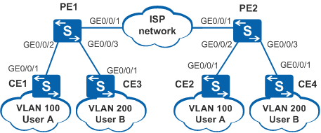
In Figure 1, CEs are edge devices on two private networks of an enterprise located in different areas, and PE1 and PE2 are edge devices on the ISP network. VLAN 100 and VLAN 200 are Layer 2 networks for different users and are connected through the ISP network. STP is run on the Layer 2 networks to prevent loops. Enterprise users require that only STP run on the private networks so that spanning trees can be generated correctly.
All the devices in VLAN 100 participate in calculation of a spanning tree.
All the devices in VLAN 200 participate in calculation of a spanning tree.
Configuration Roadmap
The configuration roadmap is as follows:
Configure STP on CEs to prevent loops on Layer 2 networks.
Configure CEs to send STP BPDUs with specified VLAN tags to PEs so that calculation of a spanning tree is complete independently in VLAN 100 and VLAN 200.
Configure VLAN-based Layer 2 protocol tunneling on PEs so that STP BPDUs are not sent to the CPUs of PEs for processing.
Procedure
- Enable STP on CEs.
# Configure CE1.
<HUAWEI> system-view
[HUAWEI] sysname CE1
[CE1] stp enable
# Configure CE2.
<HUAWEI> system-view
[HUAWEI] sysname CE2
[CE2] stp enable
# Configure CE3.
<HUAWEI> system-view
[HUAWEI] sysname CE3
[CE3] stp enable
# Configure CE4.
<HUAWEI> system-view
[HUAWEI] sysname CE4
[CE4] stp enable
- Configure CE1 and CE2 to send STP BPDUs with VLAN tag 100 to PEs, and configure CE3 and CE4 to send STP BPDUs with VLAN tag 200 to PEs.
# Configure CE1.
[CE1] vlan 100
[CE1-vlan100] quit
[CE1] interface gigabitethernet 0/0/1
[CE1-GigabitEthernet0/0/1] port link-type hybrid
[CE1-GigabitEthernet0/0/1] port hybrid tagged vlan 100
[CE1-GigabitEthernet0/0/1] stp bpdu vlan 100
[CE1-GigabitEthernet0/0/1] quit
# Configure CE2.
[CE2] vlan 100
[CE2-vlan100] quit
[CE2] interface gigabitethernet 0/0/1
[CE2-GigabitEthernet0/0/1] port link-type hybrid
[CE2-GigabitEthernet0/0/1] port hybrid tagged vlan 100
[CE2-GigabitEthernet0/0/1] stp bpdu vlan 100
[CE2-GigabitEthernet0/0/1] quit
# Configure CE3.
[CE3] vlan 200
[CE3-vlan200] quit
[CE3] interface gigabitethernet 0/0/1
[CE3-GigabitEthernet0/0/1] port link-type hybrid
[CE3-GigabitEthernet0/0/1] port hybrid tagged vlan 200
[CE3-GigabitEthernet0/0/1] stp bpdu vlan 200
[CE3-GigabitEthernet0/0/1] quit
# Configure CE4.
[CE4] vlan 200
[CE4-vlan200] quit
[CE4] interface gigabitethernet 0/0/1
[CE4-GigabitEthernet0/0/1] port link-type hybrid
[CE4-GigabitEthernet0/0/1] port hybrid tagged vlan 200
[CE4-GigabitEthernet0/0/1] stp bpdu vlan 200
[CE4-GigabitEthernet0/0/1] quit
- Configure PE interfaces to transparently transmit STP BPDUs of CEs to the peer ends.
# Configure PE1.
<HUAWEI> system-view
[HUAWEI] sysname PE1
[PE1] vlan 100
[PE1-vlan100] quit
[PE1] vlan 200
[PE1-vlan200] quit
[PE1] interface gigabitethernet 0/0/2
[PE1-GigabitEthernet0/0/2] port link-type hybrid
[PE1-GigabitEthernet0/0/2] port hybrid tagged vlan 100
[PE1-GigabitEthernet0/0/2] l2protocol-tunnel stp vlan 100
[PE1-GigabitEthernet0/0/2] quit
[PE1] interface gigabitethernet 0/0/3
[PE1-GigabitEthernet0/0/3] port link-type hybrid
[PE1-GigabitEthernet0/0/3] port hybrid tagged vlan 200
[PE1-GigabitEthernet0/0/3] l2protocol-tunnel stp vlan 200
[PE1-GigabitEthernet0/0/3] quit
[PE1] interface GigabitEthernet 0/0/1
[PE1-GigabitEthernet0/0/1] port link-type trunk
[PE1-GigabitEthernet0/0/1] port trunk allow-pass vlan 100 200
[PE1-GigabitEthernet0/0/1] quit
# Configure PE2.
<HUAWEI> system-view
[HUAWEI] sysname PE2
[PE2] vlan 100
[PE2-vlan100] quit
[PE2] vlan 200
[PE2-vlan200] quit
[PE2] interface gigabitethernet 0/0/2
[PE2-GigabitEthernet0/0/2] port link-type hybrid
[PE2-GigabitEthernet0/0/2] port hybrid tagged vlan 100
[PE2-GigabitEthernet0/0/2] l2protocol-tunnel stp vlan 100
[PE2-GigabitEthernet0/0/2] quit
[PE2] interface gigabitethernet 0/0/3
[PE2-GigabitEthernet0/0/3] port link-type hybrid
[PE2-GigabitEthernet0/0/3] port hybrid tagged vlan 200
[PE2-GigabitEthernet0/0/3] l2protocol-tunnel stp vlan 200
[PE2-GigabitEthernet0/0/3] quit
[PE2] interface GigabitEthernet 0/0/1
[PE2-GigabitEthernet0/0/1] port link-type trunk
[PE2-GigabitEthernet0/0/1] port trunk allow-pass vlan 100 200
[PE2-GigabitEthernet0/0/1] quit
- Configure PEs to replace the destination MAC address of STP BPDUs received from CEs.
# Configure PE1.
[PE1] l2protocol-tunnel stp group-mac 0100-0100-0100# Configure PE2.
[PE2] l2protocol-tunnel stp group-mac 0100-0100-0100 - Configure CE2 and CE4 to the priority of a switching device is 4096.
# Configure CE2.
[CE2] stp priority 4096
# Configure CE4.
[CE4] stp priority 4096
- Verify the configuration.
# After the configuration is complete, run the display l2protocol-tunnel group-mac command on PEs. You can view the protocol type or name, multicast destination MAC address, group MAC address, and priority of Layer 2 protocol packets to be transparently transmitted.
The display on PE1 is used as an example.
[PE1] display l2protocol-tunnel group-mac stp
Protocol         EncapeType ProtocolType Protocol-MAC   Group-MAC      Pri
-----------------------------------------------------------------------------
stp              llc        dsap 0x42    0180-c200-0000 0100-0100-0100 0
                            ssap 0x42
# After 30s, run the display stp command on CE1 and CE2 to view the root in the MSTP region. You can see that a spanning tree is calculated between CE1 and CE2. GE0/0/1 on CE1 is the root port and GE0/0/1 on CE2 is the designated port.
[CE1] display stp brief
 MSTID   Port                        Role  STP State     Protection
    0    GigabitEthernet0/0/1        ROOT  FORWARDING      NONE
[CE2] display stp brief MSTID Port Role STP State Protection 0 GigabitEthernet0/0/1 DESI FORWARDING NONE# After 30s, run the display stp command on CE3 and CE4 to view the root in the MSTP region. You can see that a spanning tree is calculated between CE3 and CE4. GE0/0/1 on CE3 is the root port and GE0/0/1 on CE4 is the designated port.
[CE3] display stp brief
 MSTID   Port                        Role  STP State     Protection
    0    GigabitEthernet0/0/1        ROOT  FORWARDING      NONE
[CE4] display stp brief MSTID Port Role STP State Protection 0 GigabitEthernet0/0/1 DESI FORWARDING NONE
Configuration Files
CE1 configuration file
#
sysname CE1
#
vlan batch 100
#
interface GigabitEthernet0/0/1
 port link-type hybrid
 port hybrid tagged vlan 100
 stp bpdu vlan 100
#
return
CE2 configuration file
#
sysname CE2
#
vlan batch 100
#
stp instance 0 priority 4096
#
interface GigabitEthernet0/0/1
 port link-type hybrid
 port hybrid tagged vlan 100
 stp bpdu vlan 100
#
return
CE3 configuration file
#
sysname CE3
#
vlan batch 200
#
interface GigabitEthernet0/0/1
 port link-type hybrid
 port hybrid tagged vlan 200
 stp bpdu vlan 200
#
return
CE4 configuration file
#
sysname CE4
#
vlan batch 200
#
stp instance 0 priority 4096
#
interface GigabitEthernet0/0/1
 port link-type hybrid
 port hybrid tagged vlan 200
 stp bpdu vlan 200
#
return
PE1 configuration file
#
sysname PE1
#
vlan batch 100 200
#
l2protocol-tunnel stp group-mac 0100-0100-0100
#
interface GigabitEthernet0/0/1  port link-type trunk                                                             port trunk allow-pass vlan 100 200 #
interface GigabitEthernet0/0/2
 port link-type hybrid
 port hybrid tagged vlan 100
 l2protocol-tunnel stp vlan 100
#
interface GigabitEthernet0/0/3
 port link-type hybrid
 port hybrid tagged vlan 200
 l2protocol-tunnel stp vlan 200
#
return
PE2 configuration file
#
sysname PE2
#
vlan batch 100 200
#
l2protocol-tunnel stp group-mac 0100-0100-0100
#
interface GigabitEthernet0/0/1  port link-type trunk                                                             port trunk allow-pass vlan 100 200 #
interface GigabitEthernet0/0/2
 port link-type hybrid
 port hybrid tagged vlan 100
 l2protocol-tunnel stp vlan 100
#
interface GigabitEthernet0/0/3
 port link-type hybrid
 port hybrid tagged vlan 200
 l2protocol-tunnel stp vlan 200
#
return