Example for Configuring VPLS-based Layer 2 Protocol Tunneling
Networking Requirements
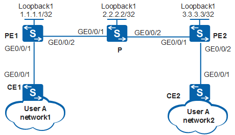
In Figure 1, CEs are located on two networks of an enterprise, and PE1 and PE2 are edge devices of the carrier network. The two networks of the enterprise are Layer 2 networks, and VPLS is used on the carrier network to construct an L2VPN to implement Layer 2 interconnection. STP is used to prevent loops on the Layer 2 network, and STP is required to run on enterprise networks to generate correct spanning trees.
Switch |
Interface |
VLANIF Interface |
IP Address |
|---|---|---|---|
PE1 |
GigabitEthernet0/0/1 |
GigabitEthernet0/0/1.1 |
- |
- |
GigabitEthernet0/0/2 |
VLANIF 20 |
4.4.4.4/24 |
- |
Loopback1 |
- |
1.1.1.1/32 |
PE2 |
GigabitEthernet0/0/1 |
VLANIF 30 |
5.5.5.5/24 |
- |
GigabitEthernet0/0/2 |
GigabitEthernet0/0/2.1 |
- |
- |
Loopback1 |
- |
3.3.3.3/32 |
P |
GigabitEthernet0/0/1 |
VLANIF 20 |
4.4.4.5/24 |
- |
GigabitEthernet0/0/2 |
VLANIF 30 |
5.5.5.4/24 |
- |
Loopback1 |
- |
2.2.2.2/32 |
CE1 |
GigabitEthernet0/0/1 |
VLANIF 10 |
10.1.1.1/24 |
CE2 |
GigabitEthernet0/0/1 |
VLANIF 10 |
10.1.1.2/24 |
Configuration Roadmap
The configuration roadmap is as follows:
Use VPLS to build an L2VPN between PE1 and PE2.
Configure STP on CEs to prevent loops on the Layer 2 network.
Create termination sub-interfaces on interfaces of CEs connected to PEs and bind sub-interfaces to VSIs so that CEs can be connected to the L2VPN.
Configure VPLS-based Layer 2 protocol tunneling on PEs so that STP BPDUs are not sent to the CPU of PEs for processing.

VLAN termination sub-interfaces cannot be created on a VCMP client.
Procedure
- Configure a VPLS-based L2VPN between PEs.
- Enable spanning tree calculation on CEs.
# Configure CE1.
[CE1] stp enable
# Configure CE2.
[CE2] stp enable
- Bind access-side sub-interfaces on PE1 and PE2 to VSIs and enable Layer 2 protocol tunneling.
# Configure PE1.
[PE1] vcmp role silent
[PE1] interface gigabitethernet
[PE1-GigabitEthernet0/0/1] port link-type hybrid
[PE1-GigabitEthernet0/0/1] quit
[PE1] interface gigabitethernet0/0/1.1
[PE1-GigabitEthernet0/0/1.1] dot1q termination vid 10
[PE1-GigabitEthernet0/0/1.1] l2 binding vsi a2
[PE1-GigabitEthernet0/0/1.1] l2protocol-tunnel stp enable
[PE1-GigabitEthernet0/0/1.1] quit
# Configure PE2.
[PE2] vcmp role silent
[PE2] interface gigabitethernet
[PE2-GigabitEthernet0/0/2] port link-type hybrid
[PE2-GigabitEthernet0/0/2] quit
[PE2] interface gigabitethernet0/0/2.1
[PE2-GigabitEthernet0/0/2.1] dot1q termination vid 10
[PE2-GigabitEthernet0/0/2.1] l2 binding vsi a2
[PE2-GigabitEthernet0/0/2.1] l2protocol-tunnel stp enable
[PE2-GigabitEthernet0/0/2.1] quit
- Configure PEs to replace the destination MAC address of STP BPDUs received from CEs.
# Configure PE1.
[PE1] l2protocol-tunnel stp group-mac 0100-0100-0100# Configure PE2.
[PE2] l2protocol-tunnel stp group-mac 0100-0100-0100 - Set the priority of CE2 to 4096.
[CE2] stp priority 4096
- Verify the configuration.
# After the configuration, run the display l2protocol-tunnel group-mac command. You can check the protocol type or name, original destination MAC address, new destination MAC address, and priority of Layer 2 protocol packets to be transparently transmitted.
The display on PE1 is used as an example.
[PE1] display l2protocol-tunnel group-mac stp
Protocol         EncapeType ProtocolType Protocol-MAC   Group-MAC      Pri
-----------------------------------------------------------------------------
stp              llc        dsap 0x42    0180-c200-0000 0100-0100-0100 0
                            ssap 0x42
# Wait for 30s and run the display stp command on CE1 and CE2 to check the root in the MST region. A spanning tree is calculated between CE1 and CE2. GE0/0/1 on CE1 is the root port, and GE0/0/1 on CE2 is the designated port.
[CE1] display stp brief
 MSTID   Port                        Role  STP State     Protection
    0    GigabitEthernet0/0/1        ROOT  FORWARDING    NONE
[CE2] display stp brief MSTID Port Role STP State Protection 0 GigabitEthernet0/0/1 DESI FORWARDING NONE
Configuration Files
CE1 configuration file
#
sysname CE1
#
vlan batch 10
#
interface Vlanif10
 ip address 10.1.1.1 255.255.255.0
#
interface GigabitEthernet0/0/1
 port link-type trunk
 port trunk allow-pass vlan 10
#
return
CE2 configuration file
#
sysname CE2
#
vlan batch 10
#
stp instance 0 priority 4096
#
interface Vlanif10
 ip address 10.1.1.2 255.255.255.0
#
interface GigabitEthernet0/0/1
 port link-type trunk
 port trunk allow-pass vlan 10
#
return
PE1 configuration file
#
sysname PE1
#
router id 1.1.1.1
#
vcmp role silent
#
vlan batch 20
#
l2protocol-tunnel stp group-mac 0100-0100-0100
#
mpls lsr-id 1.1.1.1
mpls
#
mpls l2vpn
#
vsi a2 static
 pwsignal ldp
  vsi-id 2
  peer 3.3.3.3
#
mpls ldp
#
mpls ldp remote-peer 3.3.3.3
 remote-ip 3.3.3.3
#
interface Vlanif20
 ip address 4.4.4.4 255.255.255.0
 mpls
 mpls ldp
#
interface GigabitEthernet0/0/1  port link-type hybrid
#
interface GigabitEthernet0/0/1.1
 dot1q termination vid 10
 l2 binding vsi a2
 l2protocol-tunnel stp enable
#
interface GigabitEthernet0/0/2
 port link-type hybrid
 port hybrid pvid vlan 20
 port hybrid tagged vlan 20
#
interface LoopBack1
 ip address 1.1.1.1 255.255.255.255
#
ospf 1
 area 0.0.0.0
  network 1.1.1.1 0.0.0.0
  network 4.4.4.0 0.0.0.255
#
return
P configuration file
#
sysname P
#
router id 2.2.2.2
#
vlan batch 20 30
#
mpls lsr-id 2.2.2.2
mpls
#
mpls ldp
#
interface Vlanif20
 ip address 4.4.4.5 255.255.255.0
 mpls
 mpls ldp
#
interface Vlanif30
 ip address 5.5.5.4 255.255.255.0
 mpls
 mpls ldp
#
interface GigabitEthernet0/0/1
 port link-type hybrid
 port hybrid pvid vlan 20
 port hybrid tagged vlan 20
#
interface GigabitEthernet0/0/2
 port link-type hybrid
 port hybrid pvid vlan 30
 port hybrid tagged vlan 30
#
interface LoopBack1
 ip address 2.2.2.2 255.255.255.255
#
ospf 1
 area 0.0.0.0
  network 2.2.2.2 0.0.0.0
  network 4.4.4.0 0.0.0.255
  network 5.5.5.0 0.0.0.255
#
return
PE2 configuration file
#
sysname PE2
#
router id 3.3.3.3
#
vcmp role silent
#
vlan batch 30
#
l2protocol-tunnel stp group-mac 0100-0100-0100
#
mpls lsr-id 3.3.3.3
mpls
#
mpls l2vpn
#
vsi a2 static
 pwsignal ldp
  vsi-id 2
  peer 1.1.1.1
#
mpls ldp
#
mpls ldp remote-peer 1.1.1.1
 remote-ip 1.1.1.1
#
interface Vlanif30
 ip address 5.5.5.5 255.255.255.0
 mpls
 mpls ldp
#
interface GigabitEthernet0/0/1
 port link-type hybrid
 port hybrid pvid vlan 30
 port hybrid tagged vlan 30
#
interface GigabitEthernet0/0/2  port link-type hybrid
#
interface GigabitEthernet0/0/2.1
 dot1q termination vid 10
 l2 binding vsi a2
 l2protocol-tunnel stp enable
#
interface LoopBack1
 ip address 3.3.3.3 255.255.255.255
#
ospf 1
 area 0.0.0.0
  network 3.3.3.3 0.0.0.0
  network 5.5.5.0 0.0.0.255
#
return