Example for Configuring VLL Access to L3VPN
Networking Requirements
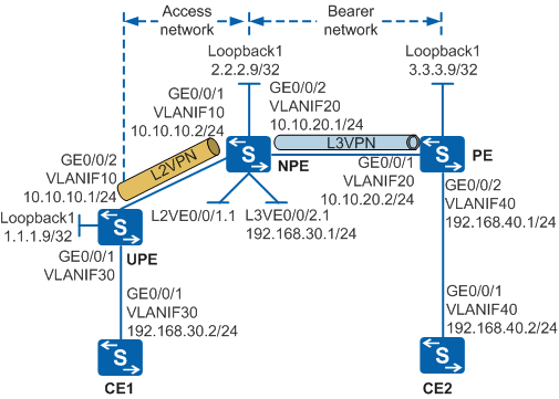
In Figure 1, the access network is an L2VPN constructed using Virtual Leased Line (VLL) and the bearer network is an L3VPN constructed using MPLS VPN. To lower the networking cost and simplify the network, the Network Provider Edge (NPE) connecting the access network and bearer network must be able to provide both L2VPN termination and L3VPN access functions. In this way, the NPE realizes the functions of both PE-AGG and NPE on the traditional network.
Configuration Roadmap
Configure an Interior Gateway Protocol (IGP) to realize route reachability. Open Shortest Path First (OSPF) is used in this example.
Configure basic MPLS LDP functions to set up LDP sessions.
On the NPE, create an L2VE interface to terminate the VLL connection, create an L3VE interface to access the L3VPN, and bind these two interfaces to the same VE group.
Configure a Martini VLL between the UPE and NPE and terminate the L2VPN on the NPE.
Configure a VPN instance on the NPE and PE to connect the L2VPN and CE2 to the L3VPN.
Set up an MP-IBGP neighbor relationship between the NPE and PE to import VPN routes.

By default, LNP is enabled globally on the device. If a VLANIF interface is used as an AC-side interface for L2VPN, the configuration conflicts with LNP. In this case, run the lnp disable command in the system view to disable LNP.
The lnp disable command has no impact on services before the device restarts. After the device restarts, the device can only forward packets from the VLANs specified by the port default vlan command at Layer 2. The port default vlan 1 command is configured by default, so only packets of VLAN 1 can be forwarded at Layer 2.
Procedure
- Specify the VLANs to which interfaces belong.
# Configure the NPE. The configurations of CE1, UPE, PE, and CE2 are similar to the configuration of the NPE.
<HUAWEI> system-view
[HUAWEI] sysname NPE
[NPE] vlan batch 10 20
[NPE] interface gigabitethernet 0/0/1
[NPE-GigabitEthernet0/0/1] port link-type trunk
[NPE-GigabitEthernet0/0/1] port trunk allow-pass vlan 10
[NPE-GigabitEthernet0/0/1] quit
[NPE] interface gigabitethernet 0/0/2
[NPE-GigabitEthernet0/0/2] port link-type trunk
[NPE-GigabitEthernet0/0/2] port trunk allow-pass vlan 20
[NPE-GigabitEthernet0/0/2] quit
- Configure VLANIF interfaces and loopback IP addresses.
# Configure the NPE. The configurations of CE1, UPE, PE, and CE2 are similar to the configuration of the NPE.
[NPE] interface vlanif 10
[NPE-Vlanif10] ip address 10.10.10.2 24
[NPE-Vlanif10] quit
[NPE] interface vlanif 20
[NPE-Vlanif20] ip address 10.10.20.1 24
[NPE-Vlanif20] quit
[NPE] interface LoopBack 1
[NPE-LoopBack1] ip address 2.2.2.9 32
[NPE-LoopBack1] quit
- Configure an IGP to realize route reachability. OSPF is used in this example. When configuring OSPF, you need to configure the UPE, NPE, and PE to advertise the IP addresses of loopback interfaces.
# Configure the UPE.
[UPE] ospf 1 router-id 1.1.1.9
[UPE-ospf-1] area 0
[UPE-ospf-1-area-0.0.0.0] network 1.1.1.9 0.0.0.0
[UPE-ospf-1-area-0.0.0.0] network 10.10.10.0 0.0.0.255
[UPE-ospf-1-area-0.0.0.0] quit
[UPE-ospf-1] quit
# Configure the NPE.
[NPE] ospf 1 router-id 2.2.2.9
[NPE-ospf-1] area 0
[NPE-ospf-1-area-0.0.0.0] network 2.2.2.9 0.0.0.0
[NPE-ospf-1-area-0.0.0.0] network 10.10.10.0 0.0.0.255
[NPE-ospf-1-area-0.0.0.0] network 10.10.20.0 0.0.0.255
[NPE-ospf-1-area-0.0.0.0] quit
[NPE-ospf-1] quit
# Configure the PE.
[PE] ospf 1 router-id 3.3.3.9
[PE-ospf-1] area 0
[PE-ospf-1-area-0.0.0.0] network 3.3.3.9 0.0.0.0
[PE-ospf-1-area-0.0.0.0] network 10.10.20.0 0.0.0.255
[PE-ospf-1-area-0.0.0.0] quit
[PE-ospf-1] quit
After the configuration is complete, OSPF neighbor relationships can be set up between the UPE, NPE, and PE. Run the display ospf peer command on the UPE, NPE, and PE, and you can see that the neighbors are in Full state. Run the display ip routing-table command on the UPE, NPE, and PE. You can see that the UPE, NPE, and PE have learned the routes to each other's loopback1 address.
- Configure basic MPLS LDP functions to set up LDP sessions.
# Enable MPLS and MPLS LDP on the UPE.
[UPE] mpls lsr-id 1.1.1.9
[UPE] mpls
[UPE-mpls] quit
[UPE] mpls ldp
[UPE-mpls-ldp] quit
[UPE] interface vlanif 10
[UPE-Vlanif10] mpls
[UPE-Vlanif10] mpls ldp
[UPE-Vlanif10] quit
# Enable MPLS and MPLS LDP on the NPE.
[NPE] mpls lsr-id 2.2.2.9
[NPE] mpls
[NPE-mpls] quit
[NPE] mpls ldp
[NPE-mpls-ldp] quit
[NPE] interface vlanif 10
[NPE-Vlanif10] mpls
[NPE-Vlanif10] mpls ldp
[NPE-Vlanif10] quit
[NPE] interface vlanif 20
[NPE-Vlanif20] mpls
[NPE-Vlanif20] mpls ldp
[NPE-Vlanif20] quit
# Enable MPLS and MPLS LDP on the PE.
[PE] mpls lsr-id 3.3.3.9
[PE] mpls
[PE-mpls] quit
[PE] mpls ldp
[PE-mpls-ldp] quit
[PE] interface vlanif 20
[PE-Vlanif20] mpls
[PE-Vlanif20] mpls ldp
[PE-Vlanif20] quit
# After the configurations are complete, LDP sessions can be set up between the UPE and NPE and between the NPE and PE. After running the display mpls ldp session command, you can view that the status of the LDP sessions is Operational. The command output on the UPE is used as an example.
[UPE] display mpls ldp session
 LDP Session(s) in Public Network
 Codes: LAM(Label Advertisement Mode), SsnAge Unit(DDDD:HH:MM)
 A '*' before a session means the session is being deleted.
 ------------------------------------------------------------------------------
 PeerID            Status      LAM  SsnRole  SsnAge       KASent/Rcv
 ------------------------------------------------------------------------------
 2.2.2.9:0          Operational DU   Passive  0000:00:01  6/6
 ------------------------------------------------------------------------------
 TOTAL: 1 session(s) Found.
- On the NPE, create an L2VE interface to terminate the L2VPN connection, create an L3VE interface to access the L3VPN, and bind these two interfaces to the same VE group.
# Create an L2VE interface to terminate the L2VPN connection.
[NPE] interface Virtual-Ethernet 0/0/1
[NPE-Virtual-Ethernet0/0/1] ve-group 1 l2-terminate
[NPE-Virtual-Ethernet0/0/1] quit
# Create an L3VE interface to access the L3VPN.
[NPE] interface Virtual-Ethernet 0/0/2
[NPE-Virtual-Ethernet0/0/2] ve-group 1 l3-access
[NPE-Virtual-Ethernet0/0/2] quit
# After the configurations are complete, run the display virtual-ethernet ve-group command on the NPE. You can find that the binding relationship between the two VE interfaces and the VE group is established.
[NPE] display virtual-ethernet ve-group
 Ve-groupID    TerminateVE                 AccessVE
 1             Virtual-Ethernet0/0/1(L2)   Virtual-Ethernet0/0/2(L3)
Total 1, 1 printed
- Configure a Martini VLL between the UPE and NPE and terminate the L2VPN on the NPE.
# Configure the UPE. Create a VC on VLANIF30 of the UPE.
[UPE] mpls l2vpn
[UPE-l2vpn] quit
[UPE] interface vlanif 30
[UPE-Vlanif30] mpls l2vc 2.2.2.9 101
[UPE-Vlanif30] quit
# Configure the NPE. Configure a dot1q VLAN ID on the L2VE sub-interface and create a VC.
[NPE] mpls l2vpn
[NPE-l2vpn] quit
[NPE] interface Virtual-Ethernet 0/0/1.1
[NPE-Virtual-Ethernet0/0/1.1] dot1q termination vid 30
[NPE-Virtual-Ethernet0/0/1.1] mpls l2vc 1.1.1.9 101
[NPE-Virtual-Ethernet0/0/1.1] quit
- Configure a VPN instance on the NPE and PE to connect the L2VPN and CE2 to the L3VPN.
# Configure the NPE. Create a VPN instance, configure a dot1q VLAN ID on the L3VE sub-interface, bind the VPN instance to the L3VE sub-interface, and configure an IP address.
[NPE] ip vpn-instance vpna
[NPE-vpn-instance-vpna] route-distinguisher 100:1
[NPE-vpn-instance-vpna-af-ipv4] vpn-target 111:1 both
[NPE-vpn-instance-vpna-af-ipv4] quit
[NPE-vpn-instance-vpna] quit
[NPE] interface Virtual-Ethernet 0/0/2.1
[NPE-Virtual-Ethernet0/0/2.1] dot1q termination vid 30
[NPE-Virtual-Ethernet0/0/2.1] ip binding vpn-instance vpna
[NPE-Virtual-Ethernet0/0/2.1] ip address 192.168.30.1 24
[NPE-Virtual-Ethernet0/0/2.1] quit
# Configure the PE. Create a VPN instance, bind the VPN instance to a VLANIF interface, and configure an IP address.
[PE] ip vpn-instance vpna
[PE-vpn-instance-vpna] route-distinguisher 200:1
[PE-vpn-instance-vpna-af-ipv4] vpn-target 111:1 both
[PE-vpn-instance-vpna-af-ipv4] quit
[PE-vpn-instance-vpna] quit
[PE] interface vlanif 40
[PE-Vlanif40] ip binding vpn-instance vpna
[PE-Vlanif40] ip address 192.168.40.1 24
[PE-Vlanif40] quit
- Set up an MP-IBGP neighbor relationship between the NPE and PE to import VPN routes.
# Configure the NPE.
[NPE] bgp 100
[NPE-bgp] peer 3.3.3.9 as-number 100
[NPE-bgp] peer 3.3.3.9 connect-interface loopback 1
[NPE-bgp] ipv4-family vpnv4
[NPE-bgp-af-vpnv4] peer 3.3.3.9 enable
[NPE-bgp-af-vpnv4] quit
[NPE-bgp] ipv4-family vpn-instance vpna
[NPE-bgp-vpna] import-route direct
[NPE-bgp-vpna] quit
[NPE-bgp] quit
# Configure the PE.
[PE] bgp 100
[PE-bgp] peer 2.2.2.9 as-number 100
[PE-bgp] peer 2.2.2.9 connect-interface loopback 1
[PE-bgp] ipv4-family vpnv4
[PE-bgp-af-vpnv4] peer 2.2.2.9 enable
[PE-bgp-af-vpnv4] quit
[PE-bgp] ipv4-family vpn-instance vpna
[PE-bgp-vpna] import-route direct
[PE-bgp-vpna] quit
[PE-bgp] quit
# After the configurations are complete, run the display bgp vpnv4 all peer command on the NPE. You can see that a BGP peer relationship has been set up between the NPE and PE and is in Established state.
[NPE] display bgp vpnv4 all peer
BGP local router ID : 2.2.2.9
 Local AS number : 100
 Total number of peers : 1                 Peers in established state : 1

  Peer            V    AS  MsgRcvd  MsgSent    OutQ  Up/Down    State        PrefRcv

  3.3.3.9         4   100   12      18         0     00:09:38   Established   0
- Verify the configuration.
# Run the display ip routing-table vpn-instance command on the PE. You can view the routes to the remote CE. The command output on the PE is used as an example.
[PE] display ip routing-table vpn-instance vpna
Route Flags: R - relay, D - download to fib, T - to vpn-instance
------------------------------------------------------------------------------
Routing Tables: vpna
         Destinations : 3        Routes : 3

Destination/Mask     Proto    Pre  Cost     Flags NextHop         Interface

 192.168.40.0/24     Direct   0    0        D     192.168.40.1    Vlanif40
 192.168.40.1/32     Direct   0    0        D     127.0.0.1       Vlanif40
 192.168.30.0/24     IBGP     255  0        RD    2.2.2.9         Vlanif20
# CE1 and CE2 can successfully ping the IP address of the L3VE sub-interface on the NPE. CE1 and CE2 can successfully ping each other. The ping result from CE1 to CE2 is used as an example.
[CE1] ping 192.168.40.2
  PING 192.168.40.2: 56  data bytes, press CTRL_C to break
    Reply from 192.168.40.2: bytes=56 Sequence=1 ttl=253 time=72 ms
    Reply from 192.168.40.2: bytes=56 Sequence=2 ttl=253 time=34 ms
    Reply from 192.168.40.2: bytes=56 Sequence=3 ttl=253 time=50 ms
    Reply from 192.168.40.2: bytes=56 Sequence=4 ttl=253 time=50 ms
    Reply from 192.168.40.2: bytes=56 Sequence=5 ttl=253 time=34 ms
  --- 192.168.40.2 ping statistics ---
    5 packet(s) transmitted
    5 packet(s) received
    0.00% packet loss
    round-trip min/avg/max = 34/48/72 ms
Configuration Files
UPE configuration file
#
sysname UPE
#
vlan batch 10 30
#
lnp disable #mpls lsr-id 1.1.1.9
mpls
#
mpls l2vpn
#
mpls ldp
#
interface Vlanif10
 ip address 10.10.10.1 255.255.255.0
 mpls
 mpls ldp
#
interface Vlanif30
 mpls l2vc 2.2.2.9 101
#
interface GigabitEthernet0/0/1
 port link-type trunk
 port trunk allow-pass vlan 30
#
interface GigabitEthernet0/0/2
 port link-type trunk
 port trunk allow-pass vlan 10
#
interface LoopBack1
 ip address 1.1.1.9 255.255.255.255
#
ospf 1 router-id 1.1.1.9
 area 0.0.0.0
  network 1.1.1.9 0.0.0.0
  network 10.10.10.0 0.0.0.255
#
return
NPE configuration file
#
sysname NPE
#
vlan batch 10 20
#
ip vpn-instance vpna
 ipv4-family
  route-distinguisher 100:1
  vpn-target 111:1 export-extcommunity
  vpn-target 111:1 import-extcommunity
#
mpls lsr-id 2.2.2.9
mpls
#
mpls l2vpn
#
mpls ldp
#
interface Vlanif10
 ip address 10.10.10.2 255.255.255.0
 mpls
 mpls ldp
#
interface Vlanif20
 ip address 10.10.20.1 255.255.255.0
 mpls
 mpls ldp
#
interface GigabitEthernet0/0/1
 port link-type trunk
 port trunk allow-pass vlan 10
#
interface GigabitEthernet0/0/2
 port link-type trunk
 port trunk allow-pass vlan 20
#
interface Virtual-Ethernet0/0/1
 ve-group 1 l2-terminate
#
interface Virtual-Ethernet0/0/1.1
 dot1q termination vid 30
 mpls l2vc 1.1.1.9 101
#
interface Virtual-Ethernet0/0/2
 ve-group 1 l3-access
#
interface Virtual-Ethernet0/0/2.1
 dot1q termination vid 30
 ip binding vpn-instance vpna
 ip address 192.168.30.1 255.255.255.0
#
interface LoopBack1
 ip address 2.2.2.9 255.255.255.255
#
bgp 100
 peer 3.3.3.9 as-number 100
 peer 3.3.3.9 connect-interface LoopBack1
 #
 ipv4-family unicast
  undo synchronization
  peer 3.3.3.9 enable
 #
 ipv4-family vpnv4
  policy vpn-target
  peer 3.3.3.9 enable
 #
 ipv4-family vpn-instance vpna
  import-route direct
#
ospf 1 router-id 2.2.2.9
 area 0.0.0.0
  network 2.2.2.9 0.0.0.0
  network 10.10.10.0 0.0.0.255
  network 10.10.20.0 0.0.0.255
#
return
PE configuration file
#
sysname PE
#
vlan batch 20 40
#
ip vpn-instance vpna
 ipv4-family
  route-distinguisher 200:1
  vpn-target 111:1 export-extcommunity
  vpn-target 111:1 import-extcommunity
#
mpls lsr-id 3.3.3.9
mpls
#
mpls ldp
#
interface Vlanif20
 ip address 10.10.20.2 255.255.255.0
 mpls
 mpls ldp
#
interface Vlanif40
 ip binding vpn-instance vpna
 ip address 192.168.40.1 255.255.255.0
#
interface GigabitEthernet0/0/1
 port link-type trunk
 port trunk allow-pass vlan 20
#
interface GigabitEthernet0/0/2
 port link-type trunk
 port trunk allow-pass vlan 40
#
interface LoopBack1
 ip address 3.3.3.9 255.255.255.255
#
bgp 100
 peer 2.2.2.9 as-number 100
 peer 2.2.2.9 connect-interface LoopBack1
 #
 ipv4-family unicast
  undo synchronization
  peer 2.2.2.9 enable
 #
 ipv4-family vpnv4
  policy vpn-target
  peer 2.2.2.9 enable
 #
 ipv4-family vpn-instance vpna
  import-route direct
#
ospf 1 router-id 3.3.3.9
 area 0.0.0.0
  network 3.3.3.9 0.0.0.0
  network 10.10.20.0 0.0.0.255
#
return
CE1 configuration file
#
sysname CE1
#
vlan batch 30
#
interface Vlanif30
 ip address 192.168.30.2 255.255.255.0
#
interface GigabitEthernet0/0/1
 port link-type trunk
 port trunk allow-pass vlan 30
#
ip route-static 0.0.0.0 0.0.0.0 192.168.30.1
#
return
CE2 configuration file
#
sysname CE2
#
vlan batch 40
#
interface Vlanif40
 ip address 192.168.40.2 255.255.255.0
#
interface GigabitEthernet0/0/1
 port link-type trunk
 port trunk allow-pass vlan 40
#
ip route-static 0.0.0.0 0.0.0.0 192.168.40.1
#
return