Example for Configuring Hub and Spoke
Networking Requirements
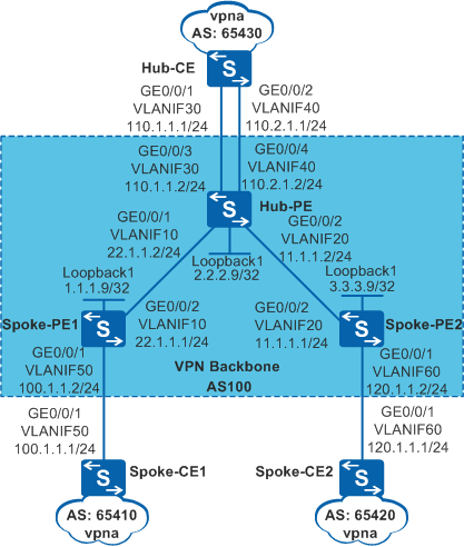
A bank wants to realize secure communication between its headquarters and branches through MPLS VPN. VPN traffic from branches passes the headquarters so that the headquarters can monitor the traffic. The Hub and Spoke networking can meet the bank's needs. As shown in Figure 1, the Spoke-CEs connect to branches, and the Hub-CE connects to the headquarters. All traffic transmitted between Spoke-CEs is forwarded by the Hub-CE.

In this scenario, to avoid loops, ensure that all connected interfaces have STP disabled and connected interfaces are removed from VLAN 1. If STP is enabled and VLANIF interfaces of switches are used to construct a Layer 3 ring network, an interface on the network will be blocked. As a result, Layer 3 services on the network cannot run normally.
Configuration Roadmap
The configuration roadmap is as follows:
- Configure an IGP protocol on the backbone network to enable the Hub-PE and Spoke-PEs to communicate with each other.
- Configure basic MPLS capabilities and MPLS LDP on the backbone network to establish LDP LSPs.
Establish MP-IBGP peer relationships between the Hub-PE and the Spoke-PEs. The Spoke-PEs do not need to establish an MP-IBGP peer relationship or exchange VPN routing information.
Create two VPN instances on the Hub-PE. One is used to receive routes from Spoke-PEs, and the other is used to advertise routes to the Spoke-PEs. Set import target of the first VPN instance to 100:1 and the export target of the other VPN instance to 200:1.
Create VPN instances on the Spoke-PEs. Set the export target of the VPN instance to 100:1 and the import target to 200:1.
Configure EBGP on the CEs and PEs to enable them to exchange VPN routing information. Configure the Hub-PE to accept one route update message with the same AS number as the local AS number and to accept the routes advertised by the Hub-CE.
Procedure
- Configure VLANs on interfaces and assign IP addresses to the VLANIF interfaces and loopback interfaces according to Figure 1.
# Configure Spoke-PE1.
<HUAWEI> system-view
[HUAWEI] sysname Spoke-PE1
[Spoke-PE1] interface loopback 1
[Spoke-PE1-LoopBack1] ip address 1.1.1.9 32
[Spoke-PE1-LoopBack1] quit
[Spoke-PE1] vlan batch 10 50
[Spoke-PE1] interface gigabitethernet 0/0/1
[Spoke-PE1-GigabitEthernet0/0/1] port link-type trunk
[Spoke-PE1-GigabitEthernet0/0/1] port trunk allow-pass vlan 50
[Spoke-PE1-GigabitEthernet0/0/1] quit
[Spoke-PE1] interface gigabitethernet 0/0/2
[Spoke-PE1-GigabitEthernet0/0/2] port link-type trunk
[Spoke-PE1-GigabitEthernet0/0/2] port trunk allow-pass vlan 10
[Spoke-PE1-GigabitEthernet0/0/2] quit
[Spoke-PE1] interface vlanif 10
[Spoke-PE1-Vlanif10] ip address 22.1.1.1 255.255.255.0
[Spoke-PE1-Vlanif10] quit
The configuration on Hub-CE, Hub-PE, Spoke-PE2, Spoke-CE1 and Spoke-CE2 is similar to the configuration on PE1 and is not mentioned here.
- Configure OSPF on the backbone network to enable the Hub-PE and Spoke-PEs to communicate with each other.
# Configure Spoke-PE1.
[Spoke-PE1] ospf 1
[Spoke-PE1-ospf-1] area 0
[Spoke-PE1-ospf-1-area-0.0.0.0] network 22.1.1.0 0.0.0.255
[Spoke-PE1-ospf-1-area-0.0.0.0] network 1.1.1.9 0.0.0.0
[Spoke-PE1-ospf-1-area-0.0.0.0] quit
[Spoke-PE1-ospf-1] quit
The configuration on the Hub-PE and Spoke-PE2 is similar to the configuration on Spoke-PE1 and is not mentioned here.
After the configuration is complete, the Hub-PE can establish OSPF neighbor relationships with Spoke-PEs. Run the display ospf peer command on the Spoke-PEs. The command output shows that the status of OSPF neighbor relationships is Full. Run the display ip routing-table command. The command output shows that the Hub-PE and Spoke-PEs have learned the route to the loopback interface of each other.
- Configure basic MPLS capabilities and MPLS LDP on the backbone network to establish LDP LSPs.
# Configure the Hub-PE.
[Hub-PE] mpls lsr-id 2.2.2.9
[Hub-PE] mpls
[Hub-PE-mpls] label advertise non-null
[Hub-PE-mpls] quit
[Hub-PE] mpls ldp
[Hub-PE-mpls-ldp] quit
[Hub-PE] interface vlanif 10
[Hub-PE-Vlanif10] mpls
[Hub-PE-Vlanif10] mpls ldp
[Hub-PE-Vlanif10] quit
[Hub-PE] interface vlanif 20
[Hub-PE-Vlanif20] mpls
[Hub-PE-Vlanif20] mpls ldp
[Hub-PE-Vlanif20] quit
# The configuration on Spoke-PEs is similar to the configuration on the Hub-PE and is not mentioned here.
After the configuration is complete, the Hub-PE can establish LDP peer relationships with the Spoke-PEs. Run the display mpls ldp session command on the Spoke-PEs. The command output shows that the session status is Operational. Run the display mpls ldp lsp command. Information about the established LDP LSPs is displayed.
- Configure VPN instances on PEs and bind the interfaces connected to CEs to the VPN instances.
The import target of the VPN instances on the Hub-PE is the export target of the VPN instance on the Spoke-PEs. The import target and export target on the Hub-PE are different. The import VPN target on the Spoke-PEs is the export VPN target on the Hub-PE.
# Configure Spoke-PE1.
[Spoke-PE1] ip vpn-instance vpna
[Spoke-PE1-vpn-instance-vpna] ipv4-family
[Spoke-PE1-vpn-instance-vpna-af-ipv4] route-distinguisher 100:1
[Spoke-PE1-vpn-instance-vpna-af-ipv4] vpn-target 100:1 export-extcommunity
[Spoke-PE1-vpn-instance-vpna-af-ipv4] vpn-target 200:1 import-extcommunity
[Spoke-PE1-vpn-instance-vpna-af-ipv4] quit
[Spoke-PE1-vpn-instance-vpna] quit
[Spoke-PE1] interface vlanif 50
[Spoke-PE1-Vlanif50] ip binding vpn-instance vpna
[Spoke-PE1-Vlanif50] ip address 100.1.1.2 24
[Spoke-PE1-Vlanif50] quit
#Configure Spoke-PE2.
[Spoke-PE2] ip vpn-instance vpna
[Spoke-PE2-vpn-instance-vpna] ipv4-family
[Spoke-PE2-vpn-instance-vpna-af-ipv4] route-distinguisher 100:3
[Spoke-PE2-vpn-instance-vpna-af-ipv4] vpn-target 100:1 export-extcommunity
[Spoke-PE2-vpn-instance-vpna-af-ipv4] vpn-target 200:1 import-extcommunity
[Spoke-PE2-vpn-instance-vpna-af-ipv4] quit
[Spoke-PE2-vpn-instance-vpna] quit
[Spoke-PE2] interface vlanif 60
[Spoke-PE2-Vlanif60] ip binding vpn-instance vpna
[Spoke-PE2-Vlanif60] ip address 120.1.1.2 24
[Spoke-PE2-Vlanif60] quit
# Configure the Hub-PE.
[Hub-PE] ip vpn-instance vpn_in
[Hub-PE-vpn-instance-vpn_in] ipv4-family
[Hub-PE-vpn-instance-vpn_in-af-ipv4] route-distinguisher 100:21
[Hub-PE-vpn-instance-vpn_in-af-ipv4] vpn-target 100:1 import-extcommunity
[Hub-PE-vpn-instance-vpn_in-af-ipv4] quit
[Hub-PE-vpn-instance-vpn_in] quit
[Hub-PE] ip vpn-instance vpn_out
[Hub-PE-vpn-instance-vpn_out] ipv4-family
[Hub-PE-vpn-instance-vpn_out-af-ipv4] route-distinguisher 100:22
[Hub-PE-vpn-instance-vpn_out-af-ipv4] vpn-target 200:1 export-extcommunity
[Hub-PE-vpn-instance-vpn_out-af-ipv4] quit
[Hub-PE-vpn-instance-vpn_out] quit
[Hub-PE] interface vlanif 30
[Hub-PE-Vlanif30] ip binding vpn-instance vpn_in
[Hub-PE-Vlanif30] ip address 110.1.1.2 24
[Hub-PE-Vlanif30] quit
[Hub-PE] interface vlanif 40
[Hub-PE-Vlanif40] ip binding vpn-instance vpn_out
[Hub-PE-Vlanif40] ip address 110.2.1.2 24
[Hub-PE-Vlanif40] quit
# Assign IP addresses to the CE interfaces. The configuration procedure is not provided here.
After the configuration is complete, run the display ip vpn-instance verbose command on the PEs to check the configuration of VPN instances. Each PE can ping its connected CE.
If a PE has multiple interfaces bound to the same VPN instance, specify a source IP addresses by setting -a source-ip-address in the ping -vpn-instance vpn-instance-name -a source-ip-address dest-ip-address command to ping a remote CE. If the source IP address is not specified, the ping fails.
- Establish EBGP peer relationships between PEs and CEs and import VPN routes into BGP.
Configure the Hub-PE to accept one route update message with the same AS number as the local AS number. This configuration allows the Hub-PE to accept routes advertised by the Hub-CE.
# Configure Spoke-CE1.
[Spoke-CE1] bgp 65410
[Spoke-CE1-bgp] peer 100.1.1.2 as-number 100
[Spoke-CE1-bgp] import-route direct
[Spoke-CE1-bgp] quit
# Configure Spoke-PE1.
[Spoke-PE1] bgp 100
[Spoke-PE1-bgp] ipv4-family vpn-instance vpna
[Spoke-PE1-bgp-vpna] peer 100.1.1.1 as-number 65410
[Spoke-PE1-bgp-vpna] import-route direct
[Spoke-PE1-bgp-vpna] quit
[Spoke-PE1-bgp] quit
# Configure Spoke-CE2.
[Spoke-CE2] bgp 65420
[Spoke-CE2-bgp] peer 120.1.1.2 as-number 100
[Spoke-CE2-bgp] import-route direct
[Spoke-CE2-bgp] quit
#Configure Spoke-PE2.
[Spoke-PE2] bgp 100
[Spoke-PE2-bgp] ipv4-family vpn-instance vpna
[Spoke-PE2-bgp-vpna] peer 120.1.1.1 as-number 65420
[Spoke-PE2-bgp-vpna] import-route direct
[Spoke-PE2-bgp-vpna] quit
[Spoke-PE2-bgp] quit
# Configure the Hub-CE.
[Hub-CE] bgp 65430
[Hub-CE-bgp] peer 110.1.1.2 as-number 100
[Hub-CE-bgp] peer 110.2.1.2 as-number 100
[Hub-CE-bgp] import-route direct
[Hub-CE-bgp] quit
# Configure the Hub-PE.
[Hub-PE] bgp 100
[Hub-PE-bgp] ipv4-family vpn-instance vpn_in
[Hub-PE-bgp-vpn_in] peer 110.1.1.1 as-number 65430
[Hub-PE-bgp-vpn_in] import-route direct
[Hub-PE-bgp-vpn_in] quit
[Hub-PE-bgp] ipv4-family vpn-instance vpn_out
[Hub-PE-bgp-vpn_out] peer 110.2.1.1 as-number 65430
[Hub-PE-bgp-vpn_out] peer 110.2.1.1 allow-as-loop 1
[Hub-PE-bgp-vpn_out] import-route direct
[Hub-PE-bgp-vpn_out] quit
[Hub-PE-bgp] quit
After the configuration is complete, run the display bgp vpnv4 all peer command on the PEs. The command output shows that BGP peer relationships have been established between the PEs and CEs and are in Established state.
- Establish MP-IBGP peer relationships between the Spoke-PEs and Hub-PE.
The Spoke-PEs do not need to allow the repeated AS number, because the switch does not check the AS_Path attribute in the routing information advertised by the IBGP peers.
# Configure Spoke-PE1.
[Spoke-PE1] bgp 100
[Spoke-PE1-bgp] peer 2.2.2.9 as-number 100
[Spoke-PE1-bgp] peer 2.2.2.9 connect-interface loopback 1
[Spoke-PE1-bgp] ipv4-family vpnv4
[Spoke-PE1-bgp-af-vpnv4] peer 2.2.2.9 enable
[Spoke-PE1-bgp-af-vpnv4] quit
[Spoke-PE1-bgp] quit
#Configure Spoke-PE2.
[Spoke-PE2] bgp 100
[Spoke-PE2-bgp] peer 2.2.2.9 as-number 100
[Spoke-PE2-bgp] peer 2.2.2.9 connect-interface loopback 1
[Spoke-PE2-bgp] ipv4-family vpnv4
[Spoke-PE2-bgp-af-vpnv4] peer 2.2.2.9 enable
[Spoke-PE2-bgp-af-vpnv4] quit
[Spoke-PE2-bgp] quit
# Configure the Hub-PE.
[Hub-PE] bgp 100
[Hub-PE-bgp] peer 1.1.1.9 as-number 100
[Hub-PE-bgp] peer 1.1.1.9 connect-interface loopback 1
[Hub-PE-bgp] peer 3.3.3.9 as-number 100
[Hub-PE-bgp] peer 3.3.3.9 connect-interface loopback 1
[Hub-PE-bgp] ipv4-family vpnv4
[Hub-PE-bgp-af-vpnv4] peer 1.1.1.9 enable
[Hub-PE-bgp-af-vpnv4] peer 3.3.3.9 enable
[Hub-PE-bgp-af-vpnv4] quit
[Hub-PE-bgp] quit
After the configuration is complete, run the display bgp peer or display bgp vpnv4 all peer command on the PEs. The command output shows that BGP peer relationships have been established between the Spoke-PEs and the Hub-PE and are in Established state.
- Verify the configurations.
After the configuration is complete, the Spoke-CEs can ping each other. Run the tracert command on the Spoke-CEs, and you can see that the traffic between the Spoke-CEs is forwarded through the Hub-CE. You can also calculate the number of forwarding devices between the Spoke-CEs based on the TTL in the ping result.
The information displayed on Spoke-CE1 is used as an example.
[Spoke-CE1] ping 120.1.1.1
  PING 120.1.1.1: 56  data bytes, press CTRL_C to break
    Reply from 120.1.1.1: bytes=56 Sequence=1 ttl=250 time=80 ms
    Reply from 120.1.1.1: bytes=56 Sequence=2 ttl=250 time=129 ms
    Reply from 120.1.1.1: bytes=56 Sequence=3 ttl=250 time=132 ms
    Reply from 120.1.1.1: bytes=56 Sequence=4 ttl=250 time=92 ms
    Reply from 120.1.1.1: bytes=56 Sequence=5 ttl=250 time=126 ms
  --- 120.1.1.1 ping statistics ---
    5 packet(s) transmitted
    5 packet(s) received
    0.00% packet loss
    round-trip min/avg/max = 80/111/132 ms
[Spoke-CE1] tracert 120.1.1.1 traceroute to 120.1.1.1(120.1.1.1), max hops: 30 ,packet length: 40,press CTRL _C to break 1 100.1.1.2 10 ms 2 ms 1 ms 2 110.2.1.2 < AS=100 > 10 ms 2 ms 2 ms 3 110.2.1.1 < AS=100 > 10 ms 2 ms 2 ms 4 110.1.1.2 < AS=65430 > 10 ms 2 ms 2 ms 5 120.1.1.2 < AS=100 > 10 ms 2 ms 2 ms 6 120.1.1.1 < AS=100 > 10 ms 2 ms 5 ms
Run the display bgp routing-table command on the Spoke-CEs. The command output shows the repeated AS number in AS paths of the BGP routes to the remote Spoke-CE.
The information displayed on Spoke-CE1 is used as an example.
[Spoke-CE1] display bgp routing-table

 BGP Local router ID is 100.1.1.1
 Status codes: * - valid, > - best, d - damped,
               h - history,  i - internal, s - suppressed, S - Stale
               Origin : i - IGP, e - EGP, ? - incomplete


 Total Number of Routes: 8
      Network            NextHop        MED        LocPrf    PrefVal Path/Ogn

 *>   100.1.1.0/24       0.0.0.0         0                     0      ?
                         100.1.1.2       0                     0      100?
 *>   100.1.1.1/32       0.0.0.0         0                     0      ?
 *>   110.1.1.0/24       100.1.1.2                             0      100 65430?
 *>   110.2.1.0/24       100.1.1.2                             0      100?
 *>   120.1.1.0/24       100.1.1.2                             0      100 65430
100?
 *>   127.0.0.0          0.0.0.0         0                     0      ?
 *>   127.0.0.1/32       0.0.0.0         0                     0      ?
Configuration Files
Spoke-CE1 configuration file
#
sysname Spoke-CE1
#
vlan batch 50
#
interface Vlanif50
 ip address 100.1.1.1 255.255.255.0
#
interface GigabitEthernet0/0/1
 port link-type trunk
 port trunk allow-pass vlan 50
#
bgp 65410
 peer 100.1.1.2 as-number 100
 #
 ipv4-family unicast
  undo synchronization
  import-route direct
  peer 100.1.1.2 enable
#
return
Spoke-PE1 configuration file
#
sysname Spoke-PE1
#
vlan batch 10 50
#
ip vpn-instance vpna
 ipv4-family
  route-distinguisher 100:1
  vpn-target 100:1 export-extcommunity
  vpn-target 200:1 import-extcommunity
#
mpls lsr-id 1.1.1.9
mpls
 label advertise non-null
#
mpls ldp
#
interface Vlanif10
 ip address 22.1.1.1 255.255.255.0
 mpls
 mpls ldp
#
interface Vlanif50
 ip binding vpn-instance vpna
 ip address 100.1.1.2 255.255.255.0
#
interface GigabitEthernet0/0/1
 port link-type trunk
 port trunk allow-pass vlan 50
#
interface GigabitEthernet0/0/2
 port link-type trunk
 port trunk allow-pass vlan 10
#
interface LoopBack1
 ip address 1.1.1.9 255.255.255.255
#
bgp 100
 peer 2.2.2.9 as-number 100
 peer 2.2.2.9 connect-interface LoopBack1
 #
 ipv4-family unicast
  undo synchronization
  peer 2.2.2.9 enable
 #
 ipv4-family vpnv4
  policy vpn-target
  peer 2.2.2.9 enable
 #
 ipv4-family vpn-instance vpna
  peer 100.1.1.1 as-number 65410
  import-route direct
#
ospf 1
 area 0.0.0.0
  network 22.1.1.0 0.0.0.255
  network 1.1.1.9 0.0.0.0
#
return
Spoke-PE2 configuration file
#
sysname Spoke-PE2
#
vlan batch 20 60
#
ip vpn-instance vpna
 ipv4-family
  route-distinguisher 100:3
  vpn-target 100:1 export-extcommunity
  vpn-target 200:1 import-extcommunity
#
mpls lsr-id 3.3.3.9
mpls
 label advertise non-null
#
mpls ldp
#
interface Vlanif20
 ip address 11.1.1.1 255.255.255.0
 mpls
 mpls ldp
#
interface Vlanif60
 ip binding vpn-instance vpna
 ip address 120.1.1.2 255.255.255.0
#
interface GigabitEthernet0/0/1
 port link-type trunk
 port trunk allow-pass vlan 60
#
interface GigabitEthernet0/0/2
 port link-type trunk
 port trunk allow-pass vlan 20
#
interface LoopBack1
 ip address 3.3.3.9 255.255.255.255
#
bgp 100
 peer 2.2.2.9 as-number 100
 peer 2.2.2.9 connect-interface LoopBack1
 #
 ipv4-family unicast
  undo synchronization
  peer 2.2.2.9 enable
 #
 ipv4-family vpnv4
  policy vpn-target
  peer 2.2.2.9 enable
 #
 ipv4-family vpn-instance vpna
  peer 120.1.1.1 as-number 65420
  import-route direct
#
ospf 1
 area 0.0.0.0
  network 3.3.3.9 0.0.0.0
  network 11.1.1.0 0.0.0.255
#
return
Spoke-CE2 configuration file
#
sysname Spoke-CE2
#
vlan batch 60
#
interface Vlanif60
 ip address 120.1.1.1 255.255.255.0
#
interface GigabitEthernet0/0/1
 port link-type trunk
 port trunk allow-pass vlan 60
#
bgp 65420
 peer 120.1.1.2 as-number 100
 #
 ipv4-family unicast
  undo synchronization
  import-route direct
  peer 120.1.1.2 enable
#
return
Hub-CE configuration file
#
sysname Hub-CE
#
vlan batch 30 40
#
interface Vlanif30
 ip address 110.1.1.1 255.255.255.0
#
interface Vlanif40
 ip address 110.2.1.1 255.255.255.0
#
interface GigabitEthernet0/0/1
 port link-type trunk
 port trunk allow-pass vlan 30
#
interface GigabitEthernet0/0/2
 port link-type trunk
 port trunk allow-pass vlan 40
#
bgp 65430
 peer 110.1.1.2 as-number 100
 peer 110.2.1.2 as-number 100
 #
 ipv4-family unicast
  undo synchronization
  import-route direct
  peer 110.2.1.2 enable
  peer 110.1.1.2 enable
#
return
Hub-PE configuration file
#
sysname Hub-PE
#
vlan batch 10 20 30 40
#
ip vpn-instance vpn_in
 ipv4-family
  route-distinguisher 100:21
  vpn-target 100:1 import-extcommunity
#
ip vpn-instance vpn_out
 ipv4-family
  route-distinguisher 100:22
  vpn-target 200:1 export-extcommunity
#
mpls lsr-id 2.2.2.9
mpls
 label advertise non-null
#
mpls ldp
#
interface Vlanif10
 ip address 22.1.1.2 255.255.255.0
 mpls
 mpls ldp
#
interface Vlanif20
 ip address 11.1.1.2 255.255.255.0
 mpls
 mpls ldp
#
interface Vlanif30
 ip binding vpn-instance vpn_in
 ip address 110.1.1.2 255.255.255.0
#
interface Vlanif40
 ip binding vpn-instance vpn_out
 ip address 110.2.1.2 255.255.255.0
#
interface GigabitEthernet0/0/1
 port link-type trunk
 port trunk allow-pass vlan 10
#
interface GigabitEthernet0/0/2
 port link-type trunk
 port trunk allow-pass vlan 20
#
interface GigabitEthernet0/0/3
 port link-type trunk
 port trunk allow-pass vlan 30
#
interface GigabitEthernet0/0/4
 port link-type trunk
 port trunk allow-pass vlan 40
#
interface LoopBack1
 ip address 2.2.2.9 255.255.255.255
#
bgp 100
 peer 1.1.1.9 as-number 100
 peer 1.1.1.9 connect-interface LoopBack1
 peer 3.3.3.9 as-number 100
 peer 3.3.3.9 connect-interface LoopBack1
 #
 ipv4-family unicast
  undo synchronization
  peer 1.1.1.9 enable
  peer 3.3.3.9 enable
 #
 ipv4-family vpnv4
  policy vpn-target
  peer 1.1.1.9 enable
  peer 3.3.3.9 enable
 #
 ipv4-family vpn-instance vpn_in
  peer 110.1.1.1 as-number 65430
  import-route direct
 #
 ipv4-family vpn-instance vpn_out
  peer 110.2.1.1 as-number 65430
  peer 110.2.1.1 allow-as-loop
  import-route direct
#
ospf 1
 area 0.0.0.0
  network 2.2.2.9 0.0.0.0
  network 22.1.1.0 0.0.0.255
  network 11.1.1.0 0.0.0.255
#
return