Example for Configuring Inter-AS VPN Option B
Networking Requirements
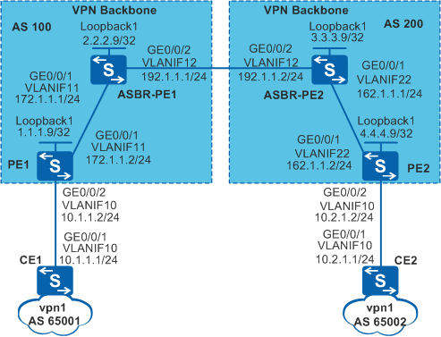
As shown in Figure 1, CE1 and CE2 belong to the same VPN. CE1 accesses PE1 through AS100, and CE2 accesses PE2 through AS200.
Inter-AS BGP/MPLS IP VPN is implemented through Option B:
ASBR-PE1 and ASBR-PE2 exchange VPNv4 routes using MP-EBGP.
ASBRs do not filter the VPNv4 routes received from each other based on VPN targets.
Configuration Roadmap
The configuration roadmap is as follows:
Configure an IGP on the MPLS backbone network to enable the ASBR and PE in the same AS to communicate with each other, and establish MPLS LDP LSPs between the ASBR and PE in the same AS.
Establish an EBGP peer relationship between the PE and CE in the same AS, and establish MP-IBGP peer relationship between the PE and ASBR-PE in the same AS.
Configure VPN instances on the PEs. (No VPN instance needs to be configured on the ASBRs.)
Enable MPLS on the interfaces connecting the ASBRs and establish an MP-EBGP peer relationship between the ASBRs. Configure the ASBRs not to filter received VPNv4 routes based on VPN targets.
Procedure
- On the MPLS backbone networks in AS 100 and AS 200, configure an IGP protocol to enable the PEs and ASBRs to communicate with each other.
Configure OSPF on the backbone networks in AS 100 and AS 200. For detailed configuration, see Example for Configuring Inter-AS VPN Option A.

The PEs and ASBRs need to advertise their LSR IDs (32-bit IP addresses of loopback interfaces) using OSPF.
After the configuration is complete, an OSPF neighbor relationship is established between the ASBR and PE in the same AS. Run the display ospf peer command to verify that the neighbor relationship is in Full state.
The ASBR-PE and PE in the same AS have obtained the loopback interface address of each other and can ping the loopback interface address of each other.
- Configure basic MPLS capabilities and MPLS LDP on the MPLS backbone networks of AS100 and AS200 to establish LDP LSPs.
For detailed configuration, refer to Example for Configuring Inter-AS VPN Option A.
- Configure VPN instances on PEs and bind the interfaces connected to CEs to the VPN instances.
The VPN targets of the VPN instances on PE1 and PE2 must match.
# Configure PE1.
[PE1] ip vpn-instance vpn1
[PE1-vpn-instance-vpn1] ipv4-family
[PE1-vpn-instance-vpn1-af-ipv4] route-distinguisher 100:1
[PE1-vpn-instance-vpn1-af-ipv4] vpn-target 1:1 export-extcommunity
[PE1-vpn-instance-vpn1-af-ipv4] vpn-target 1:1 import-extcommunity
[PE1-vpn-instance-vpn1-af-ipv4] quit
[PE1-vpn-instance-vpn1] quit
[PE1] interface vlanif 10
[PE1-Vlanif10] ip binding vpn-instance vpn1
[PE1-Vlanif10] ip address 10.1.1.2 255.255.255.0
[PE1-Vlanif10] quit
The configuration on PE2 is similar to the configuration on PE1 and is not mentioned here.
- Configure inter-AS VPN Option B.
# On ASBR-PE1, enable MPLS on VLANIF12. VLANIF12 is the interface connected to ASBR-PE2.
[ASBR-PE1] interface vlanif 12
[ASBR-PE1-Vlanif12] mpls
[ASBR-PE1-Vlanif12] quit
# On ASBR-PE1, establish an MP-EBGP peer relationship with ASBR-PE2 and disable ASBR-PE1 from filtering VPNv4 routes based on VPN targets.
[ASBR-PE1] bgp 100
[ASBR-PE1-bgp] peer 192.1.1.2 as-number 200
[ASBR-PE1-bgp] ipv4-family vpnv4
[ASBR-PE1-bgp-af-vpnv4] peer 192.1.1.2 enable
[ASBR-PE1-bgp-af-vpnv4] undo policy vpn-target
[ASBR-PE1-bgp-af-vpnv4] quit
[ASBR-PE1-bgp] quit
The configuration on ASBR-PE2 is similar to the configuration on ASBR-PE1 and is not mentioned here.
- Verify the configurations.
After the configuration is complete, CE1 and CE2 learn routes to interfaces on each other and can ping each other successfully.
The information displayed on CE1 is used as an example.
[CE1] display ip routing-table
Route Flags: R - relay, D - download to fib, T - to vpn-instance
------------------------------------------------------------------------------
Routing Tables: Public
         Destinations : 5        Routes : 5
Destination/Mask    Proto  Pre  Cost     Flags NextHop         Interface
       10.1.1.0/24  Direct 0    0             D  10.1.1.1        Vlanif10
       10.1.1.1/32  Direct 0    0             D  127.0.0.1       Vlanif10
       10.2.1.0/24  EBGP   255  0             D  10.1.1.2        Vlanif10
      127.0.0.0/8   Direct 0    0             D  127.0.0.1       InLoopBack0
      127.0.0.1/32  Direct 0    0             D  127.0.0.1       InLoopBack0
[CE1] ping 10.2.1.1 PING 10.2.1.1: 56 data bytes, press CTRL_C to break Reply from 10.2.1.1: bytes=56 Sequence=1 ttl=252 time=5 ms Reply from 10.2.1.1: bytes=56 Sequence=2 ttl=252 time=5 ms Reply from 10.2.1.1: bytes=56 Sequence=3 ttl=252 time=5 ms Reply from 10.2.1.1: bytes=56 Sequence=4 ttl=252 time=5 ms Reply from 10.2.1.1: bytes=56 Sequence=5 ttl=252 time=5 ms --- 10.2.1.1 ping statistics --- 5 packet(s) transmitted 5 packet(s) received 0.00% packet loss round-trip min/avg/max = 5/5/5 msRun the display bgp vpnv4 all routing-table command on the ASBRs to view the VPNv4 routes.
The information displayed on ASBR-PE1 is used as an example.
[ASBR-PE1] display bgp vpnv4 all routing-table


 BGP Local router ID is 2.2.2.9
 Status codes: * - valid, > - best, d - damped,
               h - history,  i - internal, s - suppressed, S - Stale
               Origin : i - IGP, e - EGP, ? - incomplete


 Total number of routes from all PE: 2
 Route Distinguisher: 100:1


      Network            NextHop        MED        LocPrf    PrefVal Path/Ogn

 *>i  10.1.1.0/24        1.1.1.9         0          100        0      ?

 Route Distinguisher: 200:1


      Network            NextHop        MED        LocPrf    PrefVal Path/Ogn

 *>   10.2.1.0/24        192.1.1.2                             0      200?
Configuration Files
CE1 configuration file
#
sysname CE1
#
vlan batch 10
#
interface Vlanif10
 ip address 10.1.1.1 255.255.255.0
#
interface GigabitEthernet0/0/1
 port link-type trunk
 port trunk allow-pass vlan 10
#
bgp 65001
 peer 10.1.1.2 as-number 100
 #
 ipv4-family unicast
  undo synchronization
  import-route direct
  peer 10.1.1.2 enable
#
return
PE1 configuration file
#
sysname PE1
#
vlan batch 10 to 11
#
ip vpn-instance vpn1
 ipv4-family
  route-distinguisher 100:1
  vpn-target 1:1 export-extcommunity
  vpn-target 1:1 import-extcommunity
#
mpls lsr-id 1.1.1.9
mpls
#
mpls ldp
#
interface Vlanif10
 ip binding vpn-instance vpn1
 ip address 10.1.1.2 255.255.255.0
#
interface Vlanif11
 ip address 172.1.1.2 255.255.255.0
 mpls
 mpls ldp
#
interface GigabitEthernet0/0/1
 port link-type trunk
 port trunk allow-pass vlan 11
#
interface GigabitEthernet0/0/2
 port link-type trunk
 port trunk allow-pass vlan 10
#
interface LoopBack1
 ip address 1.1.1.9 255.255.255.255
#
bgp 100
 peer 2.2.2.9 as-number 100
 peer 2.2.2.9 connect-interface LoopBack1
 #
 ipv4-family unicast
  undo synchronization
  peer 2.2.2.9 enable
 #
 ipv4-family vpnv4
  policy vpn-target
  peer 2.2.2.9 enable
 #
 ipv4-family vpn-instance vpn1
  peer 10.1.1.1 as-number 65001
  import-route direct
#
ospf 1
 area 0.0.0.0
  network 1.1.1.9 0.0.0.0
  network 172.1.1.0 0.0.0.255
#
return
ASBR-PE1 configuration file
#
sysname ASBR-PE1
#
vlan batch 11 to 12
#
mpls lsr-id 2.2.2.9
mpls
#
mpls ldp
#
interface Vlanif11
 ip address 172.1.1.1 255.255.255.0
 mpls
 mpls ldp
#
interface Vlanif12
 ip address 192.1.1.1 255.255.255.0
 mpls
#
interface GigabitEthernet0/0/1
 port link-type trunk
 port trunk allow-pass vlan 11
#
interface GigabitEthernet0/0/2
 port link-type trunk
 port trunk allow-pass vlan 12
#
interface LoopBack1
 ip address 2.2.2.9 255.255.255.255
#
bgp 100
 peer 192.1.1.2 as-number 200
 peer 1.1.1.9 as-number 100
 peer 1.1.1.9 connect-interface LoopBack1
 #
 ipv4-family unicast
  undo synchronization
  peer 192.1.1.2 enable
  peer 1.1.1.9 enable
 #
 ipv4-family vpnv4
  undo policy vpn-target
  peer 1.1.1.9 enable
  peer 192.1.1.2 enable
#
ospf 1
 area 0.0.0.0
  network 2.2.2.9 0.0.0.0
  network 172.1.1.0 0.0.0.255
#
return
ASBR-PE2 configuration file
#
sysname ASBR-PE2
#
vlan batch 12 22
#
mpls lsr-id 3.3.3.9
mpls
#
mpls ldp
#
interface Vlanif12
 ip address 192.1.1.2 255.255.255.0
 mpls
#
interface Vlanif22
 ip address 162.1.1.1 255.255.255.0
 mpls
 mpls ldp
#
interface GigabitEthernet0/0/1
 port link-type trunk
 port trunk allow-pass vlan 22
#
interface GigabitEthernet0/0/2
 port link-type trunk
 port trunk allow-pass vlan 12
#
interface LoopBack1
 ip address 3.3.3.9 255.255.255.255
#
bgp 200
 peer 192.1.1.1 as-number 100
 peer 4.4.4.9 as-number 200
 peer 4.4.4.9 connect-interface LoopBack1
 #
 ipv4-family unicast
  undo synchronization
  peer 192.1.1.1 enable
  peer 4.4.4.9 enable
 #
 ipv4-family vpnv4
  undo policy vpn-target
  peer 4.4.4.9 enable
  peer 192.1.1.1 enable
#
ospf 1
 area 0.0.0.0
  network 3.3.3.9 0.0.0.0
  network 162.1.1.0 0.0.0.255
#
return
PE2 configuration file
#
sysname PE2
#
vlan batch 10 22
#
ip vpn-instance vpn1
 ipv4-family
  route-distinguisher 200:1
  vpn-target 1:1 export-extcommunity
  vpn-target 1:1 import-extcommunity
#
mpls lsr-id 4.4.4.9
mpls
#
mpls ldp
#
interface Vlanif10
 ip binding vpn-instance vpn1
 ip address 10.2.1.2 255.255.255.0
#
interface Vlanif22
 ip address 162.1.1.2 255.255.255.0
 mpls
 mpls ldp
#
interface GigabitEthernet0/0/1
 port link-type trunk
 port trunk allow-pass vlan 22
#
interface GigabitEthernet0/0/2
 port link-type trunk
 port trunk allow-pass vlan 10
#
interface LoopBack1
 ip address 4.4.4.9 255.255.255.255
#
bgp 200
 peer 3.3.3.9 as-number 200
 peer 3.3.3.9 connect-interface LoopBack1
 #
 ipv4-family unicast
  undo synchronization
  peer 3.3.3.9 enable
 #
 ipv4-family vpnv4
  policy vpn-target
  peer 3.3.3.9 enable
 #
 ipv4-family vpn-instance vpn1
  peer 10.2.1.1 as-number 65002
  import-route direct
#
ospf 1
 area 0.0.0.0
  network 4.4.4.9 0.0.0.0
  network 162.1.1.0 0.0.0.255
#
return
CE2 configuration file
#
sysname CE2
#
vlan batch 10
#
interface Vlanif10
 ip address 10.2.1.1 255.255.255.0
#
interface GigabitEthernet0/0/1
 port link-type trunk
 port trunk allow-pass vlan 10
#
bgp 65002
 peer 10.2.1.2 as-number 200
 #
 ipv4-family unicast
  undo synchronization
  import-route direct
  peer 10.2.1.2 enable
#
return