Example for Configuring Static LSPs
Networking Requirements
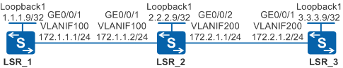
As shown in Figure 1, the network topology is simple and stable, and LSR_1, LSR_2, and LSR_3 are MPLS backbone network devices. A stable public tunnel needs to be created on the backbone network to transmit L2VPN or L3VPN services.
Configuration Roadmap
You can configure static LSPs to meet the requirement. Configure two static LSPs: LSP1 from LSR_1 to LSR_3 with LSR_1, LSR_2, and LSR_3 as the ingress, transit, and egress nodes respectively, and LSP2 from LSR_3 to LSR_1 with LSR_3, LSR_2, and LSR_1 as the ingress, transit, and egress nodes respectively. The configuration roadmap is as follows:
- Configure OSPF on the LSRs to ensure IP connectivity on the backbone network.
- Configure MPLS on LSRs, which is the prerequisite for creating a public tunnel on the backbone network.
- Configure static LSPs because a stable public tunnel needs to
be created on the backbone network with simple and stable network
topology to transmit L2VPN and L3VPN services. Perform the following
operations:
- Configure the destination IP address, next hop, value of the outgoing label for the LSP on the ingress node.
- Configure the inbound interface, value of the incoming label equivalent to the outgoing label of the last node, and next hop and value of the outgoing label of the LSP on the transit node.
- Configure the inbound interface and value of the incoming label equivalent to the outgoing label of the last node of the LSP on the egress node.
Procedure
- Create VLANs and VLANIF interfaces on the switch, configure IP addresses
for the VLANIF interfaces, and add physical interfaces to the VLANs.
# Configure LSR_1. The configurations of LSR_2 and LSR_3 are similar to the configuration of LSR_1, and are not mentioned here.
<HUAWEI> system-view
[HUAWEI] sysname LSR_1
[LSR_1] interface loopback 1
[LSR_1-LoopBack1] ip address 1.1.1.9 32
[LSR_1-LoopBack1] quit
[LSR_1] vlan batch 100
[LSR_1] interface vlanif 100
[LSR_1-Vlanif100] ip address 172.1.1.1 24
[LSR_1-Vlanif100] quit
[LSR_1] interface gigabitethernet 0/0/1
[LSR_1-GigabitEthernet0/0/1] port link-type trunk
[LSR_1-GigabitEthernet0/0/1] port trunk allow-pass vlan 100
[LSR_1-GigabitEthernet0/0/1] quit
- Configure OSPF to advertise the network segments that the
interfaces are connected to and the host route of the LSR ID.
# Configure LSR_1.
[LSR_1] ospf 1
[LSR_1-ospf-1] area 0
[LSR_1-ospf-1-area-0.0.0.0] network 1.1.1.9 0.0.0.0
[LSR_1-ospf-1-area-0.0.0.0] network 172.1.1.0 0.0.0.255
[LSR_1-ospf-1-area-0.0.0.0] quit
[LSR_1-ospf-1] quit
# Configure LSR_2.
[LSR_2] ospf 1
[LSR_2-ospf-1] area 0
[LSR_2-ospf-1-area-0.0.0.0] network 2.2.2.9 0.0.0.0
[LSR_2-ospf-1-area-0.0.0.0] network 172.1.1.0 0.0.0.255
[LSR_2-ospf-1-area-0.0.0.0] network 172.2.1.0 0.0.0.255
[LSR_2-ospf-1-area-0.0.0.0] quit
[LSR_2-ospf-1] quit
# Configure LSR_3.
[LSR_3] ospf 1
[LSR_3-ospf-1] area 0
[LSR_3-ospf-1-area-0.0.0.0] network 3.3.3.9 0.0.0.0
[LSR_3-ospf-1-area-0.0.0.0] network 172.2.1.0 0.0.0.255
[LSR_3-ospf-1-area-0.0.0.0] quit
[LSR_3-ospf-1] quit
After the configuration is complete, run the display ip routing-table command on each node, and you can view that the nodes learn routes from each other.
- Enable basic MPLS functions on each node.
# Configure LSR_1.
[LSR_1] mpls lsr-id 1.1.1.9
[LSR_1] mpls
[LSR_1-mpls] quit
# Configure LSR_2.
[LSR_2] mpls lsr-id 2.2.2.9
[LSR_2] mpls
[LSR_2-mpls] quit
# Configure LSR_3.
[LSR_3] mpls lsr-id 3.3.3.9
[LSR_3] mpls
[LSR_3-mpls] quit
- Enable MPLS on each VLANIF interface.
# Configure LSR_1.
[LSR_1] interface vlanif 100
[LSR_1-Vlanif100] mpls
[LSR_1-Vlanif100] quit
# Configure LSR_2.
[LSR_2] interface vlanif 100
[LSR_2-Vlanif100] mpls
[LSR_2-Vlanif100] quit
[LSR_2] interface vlanif 200
[LSR_2-Vlanif200] mpls
[LSR_2-Vlanif200] quit
# Configure LSR_3.
[LSR_3] interface vlanif 200
[LSR_3-Vlanif200] mpls
[LSR_3-Vlanif200] quit
- Configure a static LSP from LSR_1 to LSR_3.
# Configure ingress node LSR_1.
[LSR_1] static-lsp ingress LSP1 destination 3.3.3.9 32 nexthop 172.1.1.2 out-label 20
# Configure transit node LSR_2.
[LSR_2] static-lsp transit LSP1 incoming-interface vlanif 100 in-label 20 nexthop 172.2.1.2 out-label 40
# Configure egress node LSR_3.
[LSR_3] static-lsp egress LSP1 incoming-interface vlanif 200 in-label 40
After the configuration is complete, run the display mpls static-lsp command on each node to check the status of the static LSP. Use the command output on LSR_1 as an example.
[LSR_1] display mpls static-lsp
TOTAL          : 1       STATIC LSP(S)
UP             : 1       STATIC LSP(S)
DOWN           : 0       STATIC LSP(S)
Name            FEC                 I/O Label  I/O If                   Status
LSP1            3.3.3.9/32          NULL/20    -/Vlanif100              Up
The LSP is unidirectional, you need to configure a static LSP from LSR_3 to LSR_1.
- Configure a static LSP from LSR_3 to LSR_1.
# Configure ingress node LSR_3.
[LSR_3] static-lsp ingress LSP2 destination 1.1.1.9 32 nexthop 172.2.1.1 out-label 30
# Configure transit node LSR_2.
[LSR_2] static-lsp transit LSP2 incoming-interface vlanif 200 in-label 30 nexthop 172.1.1.1 out-label 60
# Configure egress node LSR_1.
[LSR_1] static-lsp egress LSP2 incoming-interface vlanif 100 in-label 60
- Verify the configuration.
After the configuration is complete, run the display mpls static-lsp or display mpls static-lsp verbose command on each node to check the status and detailed information about the static LSP. Use the command output on LSR_3 as an example.
[LSR_3] display mpls static-lsp
TOTAL          : 2       STATIC LSP(S)
UP             : 2       STATIC LSP(S)
DOWN           : 0       STATIC LSP(S)
Name            FEC                 I/O Label  I/O If                      Status
LSP1            -/-                 40/NULL    Vlanif200/-                 Up
LSP2            1.1.1.9/32          NULL/30    -/Vlanif200                 Up
[LSR_3] display mpls static-lsp verbose
No             : 1
LSP-Name       : LSP1
LSR-Type       : Egress
FEC            : -/-
In-Label       : 40
Out-Label      : NULL
In-Interface   : Vlanif200
Out-Interface  : -
NextHop        : -
Static-Lsp Type: Normal
Lsp Status     : Up

No             : 2
LSP-Name       : LSP2
LSR-Type       : Ingress
FEC            : 1.1.1.9/32
In-Label       : NULL
Out-Label      : 30
In-Interface   : -
Out-Interface  : Vlanif200
NextHop        : 172.2.1.1
Static-Lsp Type: Normal
Lsp Status     : Up
Run the ping lsp ip 1.1.1.9 32 command on LSR_3. The command output shows that the static LSP can be pinged.
Run the ping lsp ip 3.3.3.9 32 command on LSR_1. The command output shows that the static LSP can be pinged.
Configuration Files
LSR_1 configuration file
#
sysname LSR_1
#
vlan batch 100
#
mpls lsr-id 1.1.1.9
mpls
#
interface Vlanif100
 ip address 172.1.1.1 255.255.255.0
 mpls
#
interface GigabitEthernet0/0/1
 port link-type trunk
 port trunk allow-pass vlan 100
#
interface LoopBack1
 ip address 1.1.1.9 255.255.255.255
#
ospf 1
 area 0.0.0.0
  network 1.1.1.9 0.0.0.0
  network 172.1.1.0 0.0.0.255
#
static-lsp ingress LSP1 destination 3.3.3.9 32 nexthop 172.1.1.2 out-label 20
static-lsp egress LSP2 incoming-interface Vlanif100 in-label 60
#
return
LSR_2 configuration file
#
sysname LSR_2
#
vlan batch 100 200
#
mpls lsr-id 2.2.2.9
mpls
#
interface Vlanif100
 ip address 172.1.1.2 255.255.255.0
 mpls
#
interface Vlanif200
 ip address 172.2.1.1 255.255.255.0
 mpls
#
interface GigabitEthernet0/0/1
 port link-type trunk
 port trunk allow-pass vlan 100
#
interface GigabitEthernet0/0/2
 port link-type trunk
 port trunk allow-pass vlan 200
#
interface LoopBack1
 ip address 2.2.2.9 255.255.255.255
#
ospf 1
 area 0.0.0.0
  network 2.2.2.9 0.0.0.0
  network 172.1.1.0 0.0.0.255
  network 172.2.1.0 0.0.0.255
#
static-lsp transit LSP1 incoming-interface Vlanif100 in-label 20 nexthop 172.2.1.2 out-label 40
static-lsp transit LSP2 incoming-interface Vlanif200 in-label 30 nexthop 172.1.1.1 out-label 60
#
return
LSR_3 configuration file
#
sysname LSR_3
#
vlan batch 200
#
mpls lsr-id 3.3.3.9
mpls
#
interface Vlanif200
 ip address 172.2.1.2 255.255.255.0
 mpls
#
interface GigabitEthernet0/0/1
 port link-type trunk
 port trunk allow-pass vlan 200
#
interface LoopBack1
 ip address 3.3.3.9 255.255.255.255
#
ospf 1
 area 0.0.0.0
  network 3.3.3.9 0.0.0.0
  network 172.2.1.0 0.0.0.255
#
static-lsp egress LSP1 incoming-interface Vlanif200 in-label 40
static-lsp ingress LSP2 destination 1.1.1.9 32 nexthop 172.2.1.1 out-label 30
#
return