Example for Configuring MAC Address Limiting on an Interface
Networking Requirements
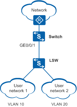
In Figure 1, user network 1 and user network 2 connect to the Switch through the LSW, and the LSW connects to the Switch through GE0/0/1. User network 1 and user network 2 belong to VLAN 10 and VLAN 20 respectively. On the Switch, MAC address limiting can be configured on GE0/0/1 to control the number of access users.
Configuration Roadmap
The configuration roadmap is as follows:
Create VLANs and add the downlink interface to the VLANs to implement Layer 2 forwarding.
Configure MAC address limiting on the interface to control the number of access users.
Procedure
- Configure MAC address limiting.
# Create VLAN 10 and VLAN 20, and add GigabitEthernet0/0/1 to VLAN 10 and VLAN 20.
<HUAWEI> system-view
[HUAWEI] sysname Switch
[Switch] vlan batch 10 20
[Switch] interface gigabitethernet 0/0/1
[Switch-GigabitEthernet0/0/1] port link-type hybrid
[Switch-GigabitEthernet0/0/1] port hybrid tagged vlan 10 20
# Configure a MAC address limiting rule on GigabitEthernet0/0/1: A maximum of 100 MAC addresses can be learned on the interface. When the number of learned MAC address entries reaches the limit, the Switch forwards packets with new source MAC addresses and generates an alarm, but does not add the new MAC address entries to the MAC address table.
[Switch-GigabitEthernet0/0/1] mac-limit maximum 100 alarm enable
[Switch-GigabitEthernet0/0/1] return
- Verify the configuration.
# Run the display mac-limit command in any view to check whether the MAC address limiting rule is successfully configured.
<Switch> display mac-limit
MAC limit is enabled
Total MAC limit rule count : 1

PORT                 VLAN/VSI         SLOT Maximum Rate(ms) Action  Alarm
----------------------------------------------------------------------------
GE0/0/1              -                -    100     -        discard enable