Example for Configuring MFF to Implement Layer 2 Isolation and Layer 3 Connection
Networking Requirements
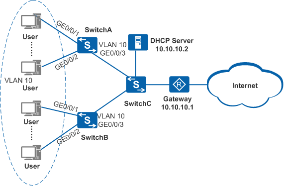
As shown in Figure 1, a department of an enterprise uses SwitchA and SwitchB as the access devices for users, and SwitchC functions as the aggregation device. The administrator requires that user hosts in VLAN 10 be isolated on the access device and communicate with each other through the gateway. This allows the gateway to monitor user traffic. When a large number of user hosts exist on the network, a DHCP server is deployed on the network to allocate IP addresses to the hosts. Forwarding heavy traffic between the application server and users will cause the gateway to overload. Therefore, the administrator configures the application server (DHCP server) to transparently transmit user traffic.
Configuration Roadmap
The configuration roadmap is as follows:
Configure DHCP snooping on SwitchA and SwitchB to provide dynamic user information such as IP address, MAC address, and VLAN to implement Layer 2 isolation and Layer 3 connection.
Configure MFF on SwitchA and SwitchB to redirect user traffic to the gateway so that users are isolated at Layer 2 and communicate with each other at Layer 3 and the gateway can monitor user traffic.
Configure the DHCP server address on SwitchA and SwitchB so that traffic from the DHCP server to users can be transparently transmitted at Layer 2. The load on gateway is relieved.
Procedure
- Create VLANs and add interfaces to the VLANs.
# Create VLAN 10 on SwitchA and add interfaces GE0/0/1, GE0/0/2, and GE0/0/3 to VLAN 10.
<HUAWEI> system-view
[HUAWEI] sysname SwitchA
[SwitchA] vlan batch 10
[SwitchA] interface gigabitethernet 0/0/1
[SwitchA-GigabitEthernet0/0/1] port link-type access
[SwitchA-GigabitEthernet0/0/1] port default vlan 10
[SwitchA-GigabitEthernet0/0/1] quit
[SwitchA] interface gigabitethernet 0/0/2
[SwitchA-GigabitEthernet0/0/2] port link-type access
[SwitchA-GigabitEthernet0/0/2] port default vlan 10
[SwitchA-GigabitEthernet0/0/2] quit
[SwitchA] interface gigabitethernet 0/0/3
[SwitchA-GigabitEthernet0/0/3] port link-type trunk
[SwitchA-GigabitEthernet0/0/3] port trunk allow-pass vlan 10
[SwitchA-GigabitEthernet0/0/3] quit
# Create VLAN 10 on SwitchB and add interfaces GE0/0/1, GE0/0/2, and GE0/0/3 to VLAN 10.
<HUAWEI> system-view
[HUAWEI] sysname SwitchB
[SwitchB] vlan batch 10
[SwitchB] interface gigabitethernet 0/0/1
[SwitchB-GigabitEthernet0/0/1] port link-type access
[SwitchB-GigabitEthernet0/0/1] port default vlan 10
[SwitchB-GigabitEthernet0/0/1] quit
[SwitchB] interface gigabitethernet 0/0/2
[SwitchB-GigabitEthernet0/0/2] port link-type access
[SwitchB-GigabitEthernet0/0/2] port default vlan 10
[SwitchB-GigabitEthernet0/0/2] quit
[SwitchB] interface gigabitethernet 0/0/3
[SwitchB-GigabitEthernet0/0/3] port link-type trunk
[SwitchB-GigabitEthernet0/0/3] port trunk allow-pass vlan 10
[SwitchB-GigabitEthernet0/0/3] quit
- Configure DHCP snooping.
# Enable DHCP snooping globally on SwitchA.
[SwitchA] dhcp enable
[SwitchA] dhcp snooping enable
# All user hosts are in VLAN 10, so enable DHCP snooping for VLAN 10 on SwitchA.
[SwitchA] vlan 10
[SwitchA-vlan10] dhcp snooping enable
[SwitchA-vlan10] quit
# Configure GE0/0/3 on SwitchA as the DHCP snooping trusted interface.
[SwitchA] interface gigabitethernet 0/0/3
[SwitchA-GigabitEthernet0/0/3] dhcp snooping trusted
[SwitchA-GigabitEthernet0/0/3] quit
# Enable DHCP snooping globally on SwitchB.
[SwitchB] dhcp enable
[SwitchB] dhcp snooping enable
# All user hosts are in VLAN 10, so enable DHCP snooping for VLAN 10 on SwitchB.
[SwitchB] vlan 10
[SwitchB-vlan10] dhcp snooping enable
[SwitchB-vlan10] quit
# Configure GE0/0/3 on SwitchB as the DHCP snooping trusted interface.
[SwitchB] interface gigabitethernet 0/0/3
[SwitchB-GigabitEthernet0/0/3] dhcp snooping trusted
[SwitchB-GigabitEthernet0/0/3] quit
- Configure MFF.
# Enable MFF globally on SwitchA.
[SwitchA] mac-forced-forwarding enable# On SwitchA, configure GE0/0/3 as an MFF network interface.
[SwitchA] interface gigabitethernet 0/0/3
[SwitchA-GigabitEthernet0/0/3] mac-forced-forwarding network-port
[SwitchA-GigabitEthernet0/0/3] quit
# Enable MFF in VLAN 10 on SwitchA.
[SwitchA] vlan 10
[SwitchA-vlan10] mac-forced-forwarding enable
# Enable MFF globally on SwitchB.
[SwitchB] mac-forced-forwarding enable# On SwitchB, configure GE0/0/3 as an MFF network interface.
[SwitchB] interface gigabitethernet 0/0/3
[SwitchB-GigabitEthernet0/0/3] mac-forced-forwarding network-port
[SwitchB-GigabitEthernet0/0/3] quit
# Enable MFF in VLAN 10 on SwitchB.
[SwitchB] vlan 10
[SwitchB-vlan10] mac-forced-forwarding enable
- Configure an IP address for the DHCP server.
# Configure a DHCP server address on SwitchA.
[SwitchA-vlan10] mac-forced-forwarding server 10.10.10.2
[SwitchA-vlan10] quit
# Configure a DHCP server address on SwitchB.
[SwitchB-vlan10] mac-forced-forwarding server 10.10.10.2
[SwitchB-vlan10] quit
- Verify the configuration.
# Run the display mac-forced-forwarding vlan 10 command to view the MFF configuration in VLAN 10. (SwitchB is used as an example.)
[SwitchB] display mac-forced-forwarding vlan 10
[Vlan 10] MFF host total count = 1
--------------------------------------------------------------------------------
Servers         10.10.10.2
--------------------------------------------------------------------------------
User IP         User MAC                Gateway IP      Gateway MAC
--------------------------------------------------------------------------------
10.10.10.11     0001-0001-0001          10.10.10.1      0002-0002-0001
--------------------------------------------------------------------------------
# Run the display mac-forced-forwarding network-port command to view the MFF network interface information. (SwitchB is used as an example.)
[SwitchB] display mac-forced-forwarding network-port
--------------------------------------------------------------------------------
VLAN ID                  Network-ports
--------------------------------------------------------------------------------
VLAN 10                  GigabitEthernet0/0/3
--------------------------------------------------------------------------------
# After the gateway interface connected to SwitchC is shut down, user hosts in VLAN 10 cannot ping each other. After the gateway interface is recovered, user hosts can ping each other. This indicates that the users are isolated at Layer 2 and communicate with each other at Layer 3. The MFF function takes effect.
Configuration Files
- SwitchA configuration
file
#
sysname SwitchA
#
vlan batch 10
#
mac-forced-forwarding enable
#
dhcp enable
#
dhcp snooping enable
#
vlan 10
 dhcp snooping enable
 mac-forced-forwarding enable
 mac-forced-forwarding server 10.10.10.2
#
interface GigabitEthernet0/0/1
 port link-type access
 port default vlan 10
#
interface GigabitEthernet0/0/2
 port link-type access
 port default vlan 10
#
interface GigabitEthernet0/0/3
 port link-type trunk
 port trunk allow-pass vlan 10
 mac-forced-forwarding network-port
 dhcp snooping trusted
#
return
- SwitchB configuration
file
#
sysname SwitchB
#
vlan batch 10
#
mac-forced-forwarding enable
#
dhcp enable
#
dhcp snooping enable
#
vlan 10
 dhcp snooping enable
 mac-forced-forwarding enable
 mac-forced-forwarding server 10.10.10.2
#
interface GigabitEthernet0/0/1
 port link-type access
 port default vlan 10
#
interface GigabitEthernet0/0/2
 port link-type access
 port default vlan 10
#
interface GigabitEthernet0/0/3
 port link-type trunk
 port trunk allow-pass vlan 10
 mac-forced-forwarding network-port
 dhcp snooping trusted
#
return