Example for Configuring Basic MLD Functions
Networking Requirements
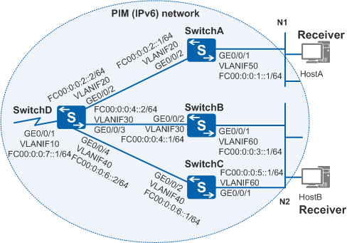
As shown in Figure 1, network segments N1 and N2 composed of different user groups exist on an IPv6 network. SwitchA connects to N1, and SwitchB and SwitchC connect to N2. The IPv6 Protocol Independent Multicast (PIM) network uses multicast addresses FF16::1 to FF16::5 to transmit video streams.
HostA on N1 and HostB on N2 want to receive video streams in multicast mode. HostA has ordered the program only from FF16::1, and HostB has ordered programs from all multicast groups. You need to perform configurations on the multicast devices to allow HostA to receive video streams only from FF16::1 and HostB to receive all video streams.

In this scenario, to avoid loops, ensure that all connected interfaces have STP disabled and connected interfaces are removed from VLAN 1. If STP is enabled and VLANIF interfaces of switches are used to construct a Layer 3 ring network, an interface on the network will be blocked. As a result, Layer 3 services on the network cannot run normally.
Configuration Roadmap
To meet the preceding requirements, configure basic MLD functions and limit the range of multicast groups that the SwitchA interface connected to N1 can join.
- To ensure that data sent from multicast sources can be correctly forwarded to the user network segments, configure an IPv6 unicast routing protocol on the network to implement IP interworking. Multicast routing protocols work depending on unicast routing protocols.
- To enable the multicast devices to forward video streams to receiver hosts in multicast mode, configure basic multicast functions on the multicast devices.
- To enable HostA to receive video streams only from FF16::1, configure a multicast policy on the SwitchA interface connected to N1 to filter multicast data.
Procedure
- Configure IPv6 addresses for interfaces and configure an IPv6 unicast routing protocol on the interfaces. The configuration details are not mentioned here.
- Configure the basic IPv6 multicast functions on each switch.
# Enable IPv6 multicast on SwitchA and enable IPv6 Protocol Independent Multicast - Sparse Mode (PIM-SM) on all its interfaces. The configurations on SwitchB, SwitchC, and SwitchD are similar to those on SwitchA and are not mentioned here.
<SwitchA> system-view
[SwitchA] multicast ipv6 routing-enable
[SwitchA] interface vlanif 20
[SwitchA-Vlanif20] pim ipv6 sm
[SwitchA-Vlanif20] quit
[SwitchA] interface vlanif 50
[SwitchA-Vlanif50] pim ipv6 sm
[SwitchA-Vlanif50] quit
# Configure the rendezvous point (RP). On SwitchD, configure VLANIF10 as a C-BSR and a C-RP.
<SwitchD> system-view
[SwitchD] pim-ipv6
[SwitchD-pim6] c-bsr fc00:0:0:7::1
[SwitchD-pim6] c-rp fc00:0:0:7::1
[SwitchD-pim6] quit
# On SwitchA, enable MLD on VLANIF50 connected to the user network segment. The configurations on SwitchB and SwitchC are similar to those on SwitchA and are not mentioned here.
[SwitchA] interface vlanif 50
[SwitchA-Vlanif50] mld enable
[SwitchA-Vlanif50] quit
- Enable VLANIF50 on SwitchA to join only multicast group FF16::1.
# Create an ACL to allow messages from only FF16::1. Apply the ACL on VLANIF50 of SwitchA.
[SwitchA] acl ipv6 number 2001
[SwitchA-acl6-basic-2001] rule permit source ff16::1 128
[SwitchA-acl6-basic-2001] quit
[SwitchA] interface vlanif 50
[SwitchA-Vlanif50] mld group-policy 2001
[SwitchA-Vlanif50] quit
- Verify the configuration.
# Run the display mld interface command to check the MLD configuration and running status on each interface of the switches. MLD information about VLANIF 50 on SwitchA is as follows:
[SwitchA] display mld interface vlanif 50 verbose
Interface information
 Vlanif50(FE80::200:5EFF:FE66:5100):
   MLD is enabled
   Current MLD version is 2
   MLD state: up
   MLD group policy: 2001
   MLD limit: -
   Value of query interval for MLD (negotiated): 125 s
   Value of query interval for MLD (configured): 125 s
   Value of other querier timeout for MLD: 0 s
   Value of maximum query response time for MLD: 10 s
   Value of last listener query time: 2 s
   Value of last listener query interval: 1 s
   Value of startup query interval: 31 s
   Value of startup query count: 2
   General query timer expiry (hours:minutes:seconds): 00:00:28
   Querier for MLD: FE80::200:5EFF:FE66:5100 (this router)
   MLD activity: 1 joins, 0 dones
   Robustness (negotiated): 2
   Robustness (configured): 2
   Require-router-alert: disabled
   Send-router-alert: enabled
   Ip-source-policy: disabled
   Query Ip-source-policy: disabled
   Prompt-leave: disabled
   SSM-Mapping: disabled
   Startup-query-timer-expiry: off
   Other-querier-present-timer-expiry: off
  Total 1 MLD Group reported
The command output shows that VLANIF50 on SwitchA is enabled with MLD and has ACL6 2001 applied. In addition, VLANIF50 has received Multicast Listener Report messages from a multicast group.
MLD information on VLANIF60 of SwitchB is as follows:
[SwitchB] display mld interface vlanif 60 verbose
Interface information
 Vlanif60(FE80::4E1F:CCFF:FE47:C8A0):
   MLD is enabled
   Current MLD version is 2
   MLD state: up
   MLD group policy: none
   MLD limit: -
   Value of query interval for MLD (negotiated): 125 s
   Value of query interval for MLD (configured): 125 s
   Value of other querier timeout for MLD: 0 s
   Value of maximum query response time for MLD: 10 s
   Value of last listener query time: 2 s
   Value of last listener query interval: 1 s
   Value of startup query interval: 31 s
   Value of startup query count: 2
   General query timer expiry (hours:minutes:seconds): 00:00:28
   Querier for MLD: FE80::4E1F:CCFF:FE47:C8A0 (this router)
   MLD activity: 2 joins, 0 dones
   Robustness (negotiated): 2
   Robustness (configured): 2
   Require-router-alert: disabled
   Send-router-alert: enabled
   Ip-source-policy: disabled
   Query Ip-source-policy: disabled
   Prompt-leave: disabled
   SSM-Mapping: disabled
   Startup-query-timer-expiry: off
   Other-querier-present-timer-expiry: off
  Total 2 MLD Groups reported
The command output shows that SwitchB is the querier. This is because the IPv6 address of VLANIF60 on SwitchB is the smallest on the network segment. In addition, VLANIF60 has received Multicast Listener Report messages from two multicast groups.
The IPv6 PIM-SM multicast routing table on SwitchB is as follows:
[SwitchB] display pim ipv6 routing-table
 VPN-Instance: public net
 Total 2 (*, G) entries; 2 (S, G) entries

 (*, FF16::1)
     RP: FC00:0:0:7::1
     Protocol: pim-sm, Flag: WC
     UpTime: 00:21:35
     Upstream interface: Vlanif30
         Upstream neighbor: FE80::A01:100:1
         RPF prime neighbor: FE80::A01:100:1
     Downstream interface(s) information:
     Total number of downstreams: 1
         1: Vlanif60
             Protocol: mld, UpTime: 00:21:35, Expires: -

 (FC00:0:0:7::5, FF16::1)
     RP: FC00:0:0:7::1
     Protocol: pim-sm, Flag: SPT ACT
     UpTime: 00:42:46
     Upstream interface: Vlanif30
         Upstream neighbor: FE80::A01:100:1
         RPF prime neighbor: FE80::A01:100:1
     Downstream interface(s) information:
     Total number of downstreams: 1
         1: Vlanif60
             Protocol: pim-sm, UpTime: 00:21:35, Expires: -

 (*, FF16::2)
     RP: FC00:0:0:7::1
     Protocol: pim-sm, Flag: WC
     UpTime: 00:06:02
     Upstream interface: Vlanif30
         Upstream neighbor: FE80::A01:100:1
         RPF prime neighbor: FE80::A01:100:1
     Downstream interface(s) information:
     Total number of downstreams: 1
         1: Vlanif60
             Protocol: mld, UpTime: 00:06:02, Expires: -

 (FC00:0:0:7::5, FF16::2)
     RP: FC00:0:0:7::1
     Protocol: pim-sm, Flag: SPT ACT
     UpTime: 00:15:12
     Upstream interface: Vlanif30
         Upstream neighbor: FE80::A01:100:1
         RPF prime neighbor: FE80::A01:100:1
     Downstream interface(s) information:
     Total number of downstreams: 1
         1: Vlanif60
             Protocol: pim-sm, UpTime: 00:06:04, Expires: -
The command output shows that (*, FF16::1), (FC00:0:0:7::5, FF16::1), (*, FF16::2), and (FC00:0:0:7::5, FF16::2) entries exist on SwitchB. This indicates that VLANIF60 has joined multicast groups FF16::1 and FF16::2, and can receive multicast data from multicast source FC00:0:0:7::5.
The IPv6 PIM-SM multicast routing table on SwitchA is as follows:
[SwitchA] display pim ipv6 routing-table
 VPN-Instance: public net
 Total 1 (*, G) entry; 1 (S, G) entry

 (*, FF16::1)
     RP: FC00:0:0:7::1
     Protocol: pim-sm, Flag: WC
     UpTime: 00:21:35
     Upstream interface: Vlanif20
         Upstream neighbor: FE80::7A1D:BAFF:FECD:909D
         RPF prime neighbor: FE80::7A1D:BAFF:FECD:909D
     Downstream interface(s) information:
     Total number of downstreams: 1
         1: Vlanif50
             Protocol: mld, UpTime: 00:21:35, Expires: -

 (FC00:0:0:7::5, FF16::1)
     RP: FC00:0:0:7::1
     Protocol: pim-sm, Flag: SPT ACT
     UpTime: 00:42:46
     Upstream interface: Vlanif20
         Upstream neighbor: FE80::7A1D:BAFF:FECD:909D
         RPF prime neighbor: FE80::7A1D:BAFF:FECD:909D
     Downstream interface(s) information:
     Total number of downstreams: 1
         1: Vlanif50
             Protocol: pim-sm, UpTime: 00:21:35, Expires: -
The command output shows that (*, FF16::1) and (FC00:0:0:7::5, FF16::1) entries exist on SwitchA. This is because an ACL is configured on VLANIF50 of SwitchA to filter out multicast data.
Configuration Files
SwitchA configuration file
#
sysname SwitchA
#
vlan batch 20 50
#
ipv6
#
multicast ipv6 routing-enable
#
acl ipv6 number 2001
 rule 0 permit source FF16::1/128
#
ospfv3 100
 router-id 10.1.1.1
#
interface Vlanif20
 ipv6 enable
 ipv6 address FC00:0:0:2::1/64
 ospfv3 100 area 0.0.0.0
 pim ipv6 sm
#
interface Vlanif50
 ipv6 enable
 ipv6 address FC00:0:0:1::1/64
 ospfv3 100 area 0.0.0.0
 pim ipv6 sm
 mld enable
 mld group-policy 2001
#
interface GigabitEthernet0/0/1
 port link-type hybrid
 port hybrid pvid vlan 50
 port hybrid untagged vlan 50
#
interface GigabitEthernet0/0/2
 port link-type trunk
 port trunk allow-pass vlan 20
#
return
SwitchB configuration file
#
sysname SwitchB
#
vlan batch 30 60
#
ipv6
#
multicast ipv6 routing-enable
#
ospfv3 100
 router-id 10.2.2.2
#
interface Vlanif30
 ipv6 enable
 ipv6 address FC00:0:0:4::1/64
 ospfv3 100 area 0.0.0.0
 pim ipv6 sm
#
interface Vlanif60
 ipv6 enable
 ipv6 address FC00:0:0:3::1/64
 ospfv3 100 area 0.0.0.0
 pim ipv6 sm
 mld enable
#
interface GigabitEthernet0/0/1
 port link-type hybrid
 port hybrid pvid vlan 60
 port hybrid untagged vlan 60
#
interface GigabitEthernet0/0/2
 port link-type trunk
 port trunk allow-pass vlan 30
#
return
SwitchC configuration file
#
sysname SwitchC
#
vlan batch 40 60
#
ipv6
#
multicast ipv6 routing-enable
#
ospfv3 100
 router-id 10.3.3.3
#
interface Vlanif40
 ipv6 enable
 ipv6 address FC00:0:0:6::1/64
 ospfv3 100 area 0.0.0.0
 pim ipv6 sm
#
interface Vlanif60
 ipv6 enable
 ipv6 address FC00:0:0:5::1/64
 ospfv3 100 area 0.0.0.0
 pim ipv6 sm
 mld enable
#
interface GigabitEthernet0/0/1
 port link-type hybrid
 port hybrid pvid vlan 60
 port hybrid untagged vlan 60
#
interface GigabitEthernet0/0/2
 port link-type trunk
 port trunk allow-pass vlan 40
#
return
SwitchD configuration file
#
sysname SwitchD
#
vlan batch 10 20 30 40
#
ipv6
#
multicast ipv6 routing-enable
#
ospfv3 100
 router-id 10.4.4.4
#
interface Vlanif10
 ipv6 enable
 ipv6 address FC00:0:0:7::1/64
 ospfv3 100 area 0.0.0.0
 pim ipv6 sm
#
interface Vlanif20
 ipv6 enable
 ipv6 address FC00:0:0:2::2/64
 ospfv3 100 area 0.0.0.0
 pim ipv6 sm
#
interface Vlanif30
 ipv6 enable
 ipv6 address FC00:0:0:4::2/64
 ospfv3 100 area 0.0.0.0
 pim ipv6 sm
#
interface Vlanif40
 ipv6 enable
 ipv6 address FC00:0:0:6::2/64
 ospfv3 100 area 0.0.0.0
 pim ipv6 sm
#
interface GigabitEthernet0/0/1
 port link-type trunk
 port trunk allow-pass vlan 10
#
interface GigabitEthernet0/0/2
 port link-type trunk
 port trunk allow-pass vlan 20
#
interface GigabitEthernet0/0/3
 port link-type trunk
 port trunk allow-pass vlan 30
#
interface GigabitEthernet0/0/4
 port link-type trunk
 port trunk allow-pass vlan 40
#
pim-ipv6
 c-bsr FC00:0:0:7::1
 c-rp FC00:0:0:7::1
#
return