Example for Configuring a Policy for Triggering LDP LSP Establishment on the Ingress and Egress Nodes
Networking Requirements
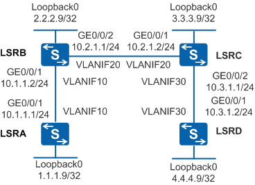
As shown in Figure 1, LSRA and LSRD are edge devices of the MPLS backbone network and have low performance. After MPLS LDP is enabled on each LSR interface, LDP LSPs are set up automatically. Because the network scale is large (this example provides two devices on intermediate nodes), many unnecessary LSPs are set up, wasting resources. The number of LSPs established on edge devices needs to be reduced so that the burden of edge devices is reduced.
Configuration Roadmap
You can configure a policy for triggering LDP LSP setup to meet the requirement. The configuration roadmap is as follows:
Configure OSPF between the LSRs to implement IP connectivity on the backbone network.
Configure local LDP sessions on LSRs so that LDP LSPs can be set up.
Configure a policy for triggering LDP LSP setup on LSRA and LSRD to reduce the number of LSPs on edge devices so that the burden of edge devices is reduced.
Procedure
- Create VLANs and VLANIF interfaces on the switch, configure IP addresses for the VLANIF interfaces, and add physical interfaces to the VLANs.
# Configure LSRA. The configurations of LSRB, LSRC, and LSRD are similar to the configuration of LSRA, and are not mentioned here.
<HUAWEI> system-view
[HUAWEI] sysname LSRA
[LSRA] interface loopback 0
[LSRA-LoopBack0] ip address 1.1.1.9 32
[LSRA-LoopBack0] quit
[LSRA] vlan batch 10
[LSRA] interface vlanif 10
[LSRA-Vlanif10] ip address 10.1.1.1 24
[LSRA-Vlanif10] quit
[LSRA] interface gigabitethernet 0/0/1
[LSRA-GigabitEthernet0/0/1] port link-type trunk
[LSRA-GigabitEthernet0/0/1] port trunk allow-pass vlan 10
[LSRA-GigabitEthernet0/0/1] quit
- Configure OSPF to advertise the network segments connecting to interfaces on each node and to advertise the routes of hosts with LSR IDs.
# Configure LSRA. The configurations of LSRB, LSRC, and LSRD are similar to the configuration of LSRA, and are not mentioned here.
[LSRA] ospf 1
[LSRA-ospf-1] area 0
[LSRA-ospf-1-area-0.0.0.0] network 1.1.1.9 0.0.0.0
[LSRA-ospf-1-area-0.0.0.0] network 10.1.1.0 0.0.0.255
[LSRA-ospf-1-area-0.0.0.0] quit
[LSRA-ospf-1] quit
- Configure basic MPLS and MPLS LDP functions on the nodes and interfaces
# Configure LSRA. The configurations of LSRB, LSRC, and LSRD are similar to the configuration of LSRA, and are not mentioned here.
[LSRA] mpls lsr-id 1.1.1.9
[LSRA] mpls
[LSRA-mpls] quit
[LSRA] mpls ldp
[LSRA-mpls-ldp] quit
[LSRA] interface vlanif 10
[LSRA-Vlanif10] mpls
[LSRA-Vlanif10] mpls ldp
[LSRA-Vlanif10] quit
# Run the display mpls lsp command on each node to view the establishment of the LDP LSPs. LSRA is used as an example.
[LSRA] display mpls lsp Flag after Out IF: (I) - LSP Is Only Iterated by RLFA ------------------------------------------------------------------------------- LSP Information: LDP LSP ------------------------------------------------------------------------------- FEC In/Out Label In/Out IF Vrf Name 1.1.1.9/32 3/NULL -/- 2.2.2.9/32 NULL/3 -/Vlanif10 2.2.2.9/32 1024/3 -/Vlanif10 3.3.3.9/32 NULL/1025 -/Vlanif10 3.3.3.9/32 1022/1025 -/Vlanif10 4.4.4.9/32 NULL/4118 -/Vlanif10 4.4.4.9/32 4105/4118 -/Vlanif10 - Configure an IP prefix list to filter routes.
# Configure an IP prefix list on LSRA that allows only 1.1.1.9/32 and 4.4.4.9/32 for LSP setup.
[LSRA] ip ip-prefix FilterOnIngress permit 1.1.1.9 32
[LSRA] ip ip-prefix FilterOnIngress permit 4.4.4.9 32
[LSRA] mpls
[LSRA-mpls] lsp-trigger ip-prefix FilterOnIngress
[LSRA-mpls] quit
# Configure an IP prefix list on LSRD that allows only 1.1.1.9/32 and 4.4.4.9/32 for LSP setup.
[LSRD] ip ip-prefix FilterOnEgress permit 1.1.1.9 32
[LSRD] ip ip-prefix FilterOnEgress permit 4.4.4.9 32
[LSRD] mpls
[LSRD-mpls] lsp-trigger ip-prefix FilterOnEgress
[LSRD-mpls] quit
- Verify the configuration.
# After the configuration is complete, run the display mpls lsp command on LSRA and LSRD to view LDP LSP establishment.
[LSRA] display mpls lsp

Flag after Out IF: (I) - LSP Is Only Iterated by RLFA
-------------------------------------------------------------------------------
                 LSP Information: LDP LSP
-------------------------------------------------------------------------------
FEC                In/Out Label  In/Out IF                      Vrf Name
1.1.1.9/32         3/NULL        -/-
2.2.2.9/32         1024/3        -/Vlanif10
3.3.3.9/32         1022/1025     -/Vlanif10
4.4.4.9/32         NULL/4118     -/Vlanif10
4.4.4.9/32         4105/4118     -/Vlanif10
After the policy is configured, there are only LDP LSPs to the destination 1.1.1.9/32 and 4.4.4.9/32 with LSRA as the ingress node and other LDP LSPs that do not use LSRA as the ingress node.
[LSRD] display mpls lsp

Flag after Out IF: (I) - LSP Is Only Iterated by RLFA
-------------------------------------------------------------------------------
                 LSP Information: LDP LSP
-------------------------------------------------------------------------------
FEC                In/Out Label  In/Out IF                      Vrf Name
1.1.1.9/32         NULL/4110     -/Vlanif30
1.1.1.9/32         4100/4110     -/Vlanif30
2.2.2.9/32         1023/1028     -/Vlanif30
3.3.3.9/32         1027/3        -/Vlanif30
4.4.4.9/32         3/NULL        -/-
After the policy is configured, there are only LDP LSPs to the destination 1.1.1.9/32 and 4.4.4.9/32 with LSRD as the ingress node and other LDP LSPs that do not use LSRD as the ingress node.
Configuration Files
LSRA configuration file
#
sysname LSRA
#
vlan batch 10
#
mpls lsr-id 1.1.1.9
mpls
 lsp-trigger ip-prefix FilterOnIngress
#
mpls ldp
#
interface Vlanif10
 ip address 10.1.1.1 255.255.255.0
 mpls
 mpls ldp
#
interface GigabitEthernet0/0/1
 port link-type trunk
 port trunk allow-pass vlan 10
#
interface LoopBack0
 ip address 1.1.1.9 255.255.255.255
#
ospf 1
 area 0.0.0.0
  network 1.1.1.9 0.0.0.0
  network 10.1.1.0 0.0.0.255
#
ip ip-prefix FilterOnIngress index 10 permit 1.1.1.9 32
ip ip-prefix FilterOnIngress index 20 permit 4.4.4.9 32
#
return
LSRB configuration file
#
sysname LSRB
#
vlan batch 10 20
#
mpls lsr-id 2.2.2.9
mpls
#
mpls ldp
#
interface Vlanif10
 ip address 10.1.1.2 255.255.255.0
 mpls
 mpls ldp
#
interface Vlanif20
 ip address 10.2.1.1 255.255.255.0
 mpls
 mpls ldp
#
interface GigabitEthernet0/0/1
 port link-type trunk
 port trunk allow-pass vlan 10
#
interface GigabitEthernet0/0/2
 port link-type trunk
 port trunk allow-pass vlan 20
#
interface LoopBack0
 ip address 2.2.2.9 255.255.255.255
#
ospf 1
 area 0.0.0.0
  network 2.2.2.9 0.0.0.0
  network 10.1.1.0 0.0.0.255
  network 10.2.1.0 0.0.0.255
#
return
LSRC configuration file
#
sysname LSRC
#
vlan batch 20 30
#
mpls lsr-id 3.3.3.9
mpls
#
mpls ldp
#
interface Vlanif20
 ip address 10.2.1.2 255.255.255.0
 mpls
 mpls ldp
#
interface Vlanif30
 ip address 10.3.1.1 255.255.255.0
 mpls
 mpls ldp
#
interface GigabitEthernet0/0/1
 port link-type trunk
 port trunk allow-pass vlan 20
#
interface GigabitEthernet0/0/2
 port link-type trunk
 port trunk allow-pass vlan 30
#
interface LoopBack0
 ip address 3.3.3.9 255.255.255.255
#
ospf 1
 area 0.0.0.0
  network 3.3.3.9 0.0.0.0
  network 10.2.1.0 0.0.0.255
  network 10.3.1.0 0.0.0.255
#
return
LSRD configuration file
#
sysname LSRD
#
vlan batch 30
#
mpls lsr-id 4.4.4.9
mpls
 lsp-trigger ip-prefix FilterOnEgress
#
mpls ldp
#
interface Vlanif30
 ip address 10.3.1.2 255.255.255.0
 mpls
 mpls ldp
#
interface GigabitEthernet0/0/1
 port link-type trunk
 port trunk allow-pass vlan 30
#
interface LoopBack0
 ip address 4.4.4.9 255.255.255.255
#
ospf 1
 area 0.0.0.0
  network 4.4.4.9 0.0.0.0
  network 10.3.1.0 0.0.0.255
#
ip ip-prefix FilterOnEgress index 10 permit 1.1.1.9 32
ip ip-prefix FilterOnEgress index 20 permit 4.4.4.9 32
#
return