Example for Disabling Devices from Distributing LDP Labels to Remote Peers
Networking Requirements
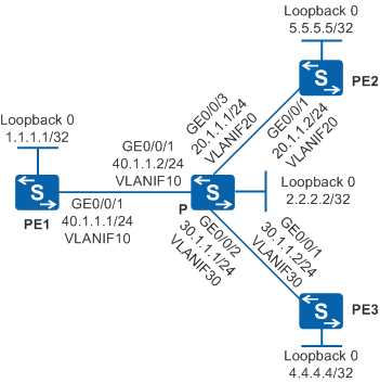
As shown in Figure 1, PE1, PE2, and PE3 connect to the P of the MPLS backbone network and IS-IS is used. Public LSPs are used to transmit L2VPN services. PE1 establishes remote LDP sessions with PE2 and PE3 to exchange private labels. Dynamic Pseudo Wires (PWs) are set up between PE1 and PE2 and between PE1 and PE3.
On an MPLS network, LDP transmits private network label and distributes common LDP labels to remote peers. Multiple remote LDP peers on the network lead to a large number of null labels, which occupies many system resources. The label distribution to remote LDP peers needs to be controlled to save system resources.
Configuration Roadmap
To meet the preceding requirements, disable devices from distributing LDP labels to remote peers. The configuration roadmap is as follows:
Configure IS-IS between on PEs and P to implement IP connectivity on the backbone network.
Configure local LDP sessions on PEs and P so that public LSPs can be set up to transmit L2VPN services.
Configure remote LDP sessions on PEs to exchange private labels so that dynamic PWs are set up.
Disable PEs from allocating labels to remote peers so that PE1 cannot allocate LDP labels to PE2 and PE3. This setting saves system resources.
Procedure
- Create VLANs and VLANIF interfaces on the switch, configure IP addresses
for the VLANIF interfaces, and add physical interfaces to the VLANs.
# Configure PE1. The configurations of P, PE2, and PE3 are similar to the configuration of PE1, and are not mentioned here.
<HUAWEI> system-view
[HUAWEI] sysname PE1
[PE1] interface loopback 0
[PE1-LoopBack0] ip address 1.1.1.1 32
[PE1-LoopBack0] quit
[PE1] vlan batch 10
[PE1] interface vlanif 10
[PE1-Vlanif10] ip address 40.1.1.1 24
[PE1-Vlanif10] quit
[PE1] interface gigabitethernet 0/0/1
[PE1-GigabitEthernet0/0/1] port link-type trunk
[PE1-GigabitEthernet0/0/1] port trunk allow-pass vlan 10
[PE1-GigabitEthernet0/0/1] quit
- Configure IS-IS to advertise the network segments connecting
to interfaces on each node and to advertise the routes of hosts with
LSR IDs.
# Configure PE1.
[PE1] isis 1
[PE1-isis-1] is-level level-2
[PE1-isis-1] network-entity 86.4501.0010.0100.0001.00
[PE1-isis-1] quit
[PE1] interface vlanif 10
[PE1-Vlanif10] isis enable 1
[PE1-Vlanif10] quit
[PE1] interface loopback 0
[PE1-LoopBack0] isis enable 1
[PE1-LoopBack0] quit
# Configure P.
[P] isis 1
[P-isis-1] is-level level-2
[P-isis-1] network-entity 86.4501.0030.0300.0003.00
[P-isis-1] quit
[P] interface vlanif 10
[P-Vlanif10] isis enable 1
[P-Vlanif10] quit
[P] interface vlanif 20
[P-Vlanif20] isis enable 1
[P-Vlanif20] quit
[P] interface vlanif 30
[P-Vlanif30] isis enable 1
[P-Vlanif30] quit
[P] interface loopback 0
[P-LoopBack0] isis enable 1
[P-LoopBack0] quit
# Configure PE2.
[PE2] isis 1
[PE2-isis-1] is-level level-2
[PE2-isis-1] network-entity 86.4501.0050.0500.0005.00
[PE2-isis-1] quit
[PE2] interface vlanif 20
[PE2-Vlanif20] isis enable 1
[PE2-Vlanif20] quit
[PE2] interface loopback 0
[PE2-LoopBack0] isis enable 1
[PE2-LoopBack0] quit
# Configure PE3.
[PE3] isis 1
[PE3-isis-1] is-level level-2
[PE3-isis-1] network-entity 86.4501.0040.0400.0004.00
[PE3-isis-1] quit
[PE3] interface vlanif 30
[PE3-Vlanif30] isis enable 1
[PE3-Vlanif30] quit
[PE3] interface loopback 0
[PE3-LoopBack0] isis enable 1
[PE3-LoopBack0] quit
- Configure local LDP sessions.
# Configure PE1.
[PE1] mpls lsr-id 1.1.1.1
[PE1] mpls
[PE1-mpls] quit
[PE1] mpls ldp
[PE1-mpls-ldp] quit
[PE1] interface vlanif 10
[PE1-Vlanif10] mpls
[PE1-Vlanif10] mpls ldp
[PE1-Vlanif10] quit
# Configure P.
[P] mpls lsr-id 2.2.2.2
[P] mpls
[P-mpls] quit
[P] mpls ldp
[P-mpls-ldp] quit
[P] interface vlanif 10
[P-Vlanif10] mpls
[P-Vlanif10] mpls ldp
[P-Vlanif10] quit
[P] interface vlanif 20
[P-Vlanif20] mpls
[P-Vlanif20] mpls ldp
[P-Vlanif20] quit
[P] interface vlanif 30
[P-Vlanif30] mpls
[P-Vlanif30] mpls ldp
[P-Vlanif30] quit
# Configure PE2.
[PE2] mpls lsr-id 5.5.5.5
[PE2] mpls
[PE2-mpls] quit
[PE2] mpls ldp
[PE2-mpls-ldp] quit
[PE2] interface vlanif 20
[PE2-Vlanif20] mpls
[PE2-Vlanif20] mpls ldp
[PE2-Vlanif20] quit
# Configure PE3.
[PE3] mpls lsr-id 4.4.4.4
[PE3] mpls
[PE3-mpls] quit
[PE3] mpls ldp
[PE3-mpls-ldp] quit
[PE3] interface vlanif 30
[PE3-Vlanif30] mpls
[PE3-Vlanif30] mpls ldp
[PE3-Vlanif30] quit
After the configuration is complete, LDP sessions and public network LSPs are established between neighboring nodes. Run the display mpls ldp session command on each node. The command output shows that the LDP session status is Operational. PE1 is used as an example
[PE1] display mpls ldp session

 LDP Session(s) in Public Network
 Codes: LAM(Label Advertisement Mode), SsnAge Unit(DDDD:HH:MM)
 A '*' before a session means the session is being deleted.
 ------------------------------------------------------------------------------
 PeerID             Status      LAM  SsnRole  SsnAge      KASent/Rcv
 ------------------------------------------------------------------------------
 2.2.2.2:0          Operational DU   Passive  0000:00:01  6/6
 ------------------------------------------------------------------------------
 TOTAL: 1 session(s) Found.
Run the display mpls ldp lsp command to check the LSP setup result and label distribution.
[PE1] display mpls ldp lsp LDP LSP Information ------------------------------------------------------------------------------- Flag after Out IF: (I) - LSP Is Only Iterated by RLFA ------------------------------------------------------------------------------- DestAddress/Mask In/OutLabel UpstreamPeer NextHop OutInterface ------------------------------------------------------------------------------- 1.1.1.1/32 3/NULL 2.2.2.2 127.0.0.1 InLoop0 *1.1.1.1/32 Liberal/1025 DS/2.2.2.2 2.2.2.2/32 NULL/3 - 40.1.1.2 Vlanif10 2.2.2.2/32 1024/3 2.2.2.2 40.1.1.2 Vlanif10 4.4.4.4/32 NULL/1024 - 40.1.1.2 Vlanif10 4.4.4.4/32 1025/1024 2.2.2.2 40.1.1.2 Vlanif10 5.5.5.5/32 NULL/1026 - 40.1.1.2 Vlanif10 5.5.5.5/32 1022/1026 2.2.2.2 40.1.1.2 Vlanif10 ------------------------------------------------------------------------------- TOTAL: 7 Normal LSP(s) Found. TOTAL: 1 Liberal LSP(s) Found. TOTAL: 0 Frr LSP(s) Found. A '*' before an LSP means the LSP is not established A '*' before a Label means the USCB or DSCB is stale A '*' before a UpstreamPeer means the session is stale A '*' before a DS means the session is stale A '*' before a NextHop means the LSP is FRR LSP - Set up the remote MPLS LDP peer relationship between PEs
at both ends of the PW.
# Configure PE1.
[PE1] mpls ldp remote-peer pe2
[PE1-mpls-ldp-remote-pe2] remote-ip 5.5.5.5
[PE1-mpls-ldp-remote-pe2] quit
[PE1] mpls ldp remote-peer pe3
[PE1-mpls-ldp-remote-pe3] remote-ip 4.4.4.4
[PE1-mpls-ldp-remote-pe3] quit
# Configure PE2.
[PE2] mpls ldp remote-peer pe1
[PE2-mpls-ldp-remote-pe1] remote-ip 1.1.1.1
[PE2-mpls-ldp-remote-pe1] quit
# Configure PE3.
[PE3] mpls ldp remote-peer pe1
[PE3-mpls-ldp-remote-pe1] remote-ip 1.1.1.1
[PE3-mpls-ldp-remote-pe1] quit
After the configuration is complete, remote LDP sessions are established between neighboring PEs. Run the display mpls ldp session command on each node. The command output shows that the LDP session status is Operational. PE1 is used as an example
[PE1] display mpls ldp session

 LDP Session(s) in Public Network
 Codes: LAM(Label Advertisement Mode), SsnAge Unit(DDDD:HH:MM)
 A '*' before a session means the session is being deleted.
 ------------------------------------------------------------------------------
 PeerID             Status      LAM  SsnRole  SsnAge      KASent/Rcv
 ------------------------------------------------------------------------------
 2.2.2.2:0          Operational DU   Passive  0000:00:18  75/75
 4.4.4.4:0          Operational DU   Passive  0000:00:10  43/43
 5.5.5.5:0          Operational DU   Passive  0000:00:12  50/50
 ------------------------------------------------------------------------------
 TOTAL: 3 session(s) Found.
Run the display mpls ldp lsp command to view the label distribution. The command output shows that PEs have distributed liberal labels to their own remote neighbors. These labels, however, are idle and occupy many system resources in MPLS L2VPN applications that use PWE3 technology.
[PE1] display mpls ldp lsp LDP LSP Information ------------------------------------------------------------------------------- Flag after Out IF: (I) - LSP Is Only Iterated by RLFA ------------------------------------------------------------------------------- DestAddress/Mask In/OutLabel UpstreamPeer NextHop OutInterface ------------------------------------------------------------------------------- 1.1.1.1/32 3/NULL 2.2.2.2 127.0.0.1 InLoop0 1.1.1.1/32 3/NULL 5.5.5.5 127.0.0.1 InLoop0 1.1.1.1/32 3/NULL 4.4.4.4 127.0.0.1 InLoop0 *1.1.1.1/32 Liberal/1025 DS/2.2.2.2 *1.1.1.1/32 Liberal/1024 DS/5.5.5.5 *1.1.1.1/32 Liberal/1025 DS/4.4.4.4 2.2.2.2/32 NULL/3 - 40.1.1.2 Vlanif10 2.2.2.2/32 1024/3 2.2.2.2 40.1.1.2 Vlanif10 2.2.2.2/32 1024/3 5.5.5.5 40.1.1.2 Vlanif10 2.2.2.2/32 1024/3 4.4.4.4 40.1.1.2 Vlanif10 *2.2.2.2/32 Liberal/1025 DS/5.5.5.5 *2.2.2.2/32 Liberal/1024 DS/4.4.4.4 4.4.4.4/32 NULL/1024 - 40.1.1.2 Vlanif10 4.4.4.4/32 1025/1024 2.2.2.2 40.1.1.2 Vlanif10 4.4.4.4/32 1025/1024 5.5.5.5 40.1.1.2 Vlanif10 4.4.4.4/32 1025/1024 4.4.4.4 40.1.1.2 Vlanif10 *4.4.4.4/32 Liberal/1026 DS/5.5.5.5 *4.4.4.4/32 Liberal/3 DS/4.4.4.4 5.5.5.5/32 NULL/1026 - 40.1.1.2 Vlanif10 5.5.5.5/32 1022/1026 2.2.2.2 40.1.1.2 Vlanif10 5.5.5.5/32 1022/1026 5.5.5.5 40.1.1.2 Vlanif10 5.5.5.5/32 1022/1026 4.4.4.4 40.1.1.2 Vlanif10 *5.5.5.5/32 Liberal/3 DS/5.5.5.5 *5.5.5.5/32 Liberal/1026 DS/4.4.4.4 ------------------------------------------------------------------------------- TOTAL: 15 Normal LSP(s) Found. TOTAL: 9 Liberal LSP(s) Found. TOTAL: 0 Frr LSP(s) Found. A '*' before an LSP means the LSP is not established A '*' before a Label means the USCB or DSCB is stale A '*' before a UpstreamPeer means the session is stale A '*' before a DS means the session is stale A '*' before a NextHop means the LSP is FRR LSP - Disable devices from distributing LDP labels to remote
peers on PEs at both ends of a PW.
# Configure PE1.
[PE1] mpls ldp remote-peer pe2
[PE1-mpls-ldp-remote-pe2] remote-ip 5.5.5.5 pwe3
[PE1-mpls-ldp-remote-pe2] quit
[PE1] mpls ldp remote-peer pe3
[PE1-mpls-ldp-remote-pe3] remote-ip 4.4.4.4 pwe3
[PE1-mpls-ldp-remote-pe3] quit
# Configure PE2.
[PE2] mpls ldp remote-peer pe1
[PE2-mpls-ldp-remote-pe1] remote-ip 1.1.1.1 pwe3
[PE2-mpls-ldp-remote-pe1] quit
# Configure PE3.
[PE3] mpls ldp remote-peer pe1
[PE3-mpls-ldp-remote-pe1] remote-ip 1.1.1.1 pwe3
[PE3-mpls-ldp-remote-pe1] quit
After the configuration is complete, PEs do not distribute labels to remote LDP peers. Run the display mpls ldp lsp command on each node to view the established LSP after devices from distributing LDP labels to remote peers is disabled. PE1 is used as an example.
[PE1] display mpls ldp lsp

 LDP LSP Information
 -------------------------------------------------------------------------------
 Flag after Out IF: (I) - LSP Is Only Iterated by RLFA
 -------------------------------------------------------------------------------
 DestAddress/Mask   In/OutLabel    UpstreamPeer    NextHop         OutInterface
 -------------------------------------------------------------------------------
 1.1.1.1/32         3/NULL         2.2.2.2         127.0.0.1       InLoop0
*1.1.1.1/32         Liberal/1024                   DS/2.2.2.2
 2.2.2.2/32         NULL/3         -               40.1.1.2        Vlanif10
 2.2.2.2/32         1025/3         2.2.2.2         40.1.1.2        Vlanif10
 4.4.4.4/32         NULL/1024      -               40.1.1.2        Vlanif10
 4.4.4.4/32         1025/1024      2.2.2.2         40.1.1.2        Vlanif10
 5.5.5.5/32         NULL/1026      -               40.1.1.2        Vlanif10
 5.5.5.5/32         1022/1026      2.2.2.2         40.1.1.2        Vlanif10
 -------------------------------------------------------------------------------
 TOTAL: 7 Normal LSP(s) Found.
 TOTAL: 1 Liberal LSP(s) Found.
 TOTAL: 0 Frr LSP(s) Found.
 A '*' before an LSP means the LSP is not established
 A '*' before a Label means the USCB or DSCB is stale
 A '*' before a UpstreamPeer means the session is stale
 A '*' before a DS means the session is stale
 A '*' before a NextHop means the LSP is FRR LSP
A large number of idle remote labels and LSPs are disabled. The LSPs are established based on the local LDP sessions.
Configuration Files
PE1 configuration file
#
sysname PE1
#
vlan batch 10
#
mpls lsr-id 1.1.1.1
mpls
#
mpls ldp
#
mpls ldp remote-peer pe2
 remote-ip 5.5.5.5 pwe3
#
mpls ldp remote-peer pe3
 remote-ip 4.4.4.4 pwe3
#
isis 1
 is-level level-2
 network-entity 86.4501.0010.0100.0001.00
#
interface Vlanif10
 ip address 40.1.1.1 255.255.255.0
 isis enable 1
 mpls
 mpls ldp
#
interface GigabitEthernet0/0/1
 port link-type trunk
 port trunk allow-pass vlan 10
#
interface LoopBack0
 ip address 1.1.1.1 255.255.255.255
 isis enable 1
#
return
P configuration file
#
sysname P
#
vlan batch 10 20 30
#
mpls lsr-id 2.2.2.2
mpls
#
mpls ldp
#
isis 1
 is-level level-2
 network-entity 86.4501.0030.0300.0003.00
#
interface Vlanif10
 ip address 40.1.1.2 255.255.255.0
 isis enable 1
 mpls
 mpls ldp
#
interface Vlanif20
 ip address 20.1.1.1 255.255.255.0
 isis enable 1
 mpls
 mpls ldp
#
interface Vlanif30
 ip address 30.1.1.1 255.255.255.0
 isis enable 1
 mpls
 mpls ldp
#
interface GigabitEthernet0/0/1
 port link-type trunk
 port trunk allow-pass vlan 10
#
interface GigabitEthernet0/0/2
 port link-type trunk
 port trunk allow-pass vlan 30
#
interface GigabitEthernet0/0/3
 port link-type trunk
 port trunk allow-pass vlan 20
#
interface LoopBack0
 ip address 2.2.2.2 255.255.255.255
 isis enable 1
#
return
PE2 configuration file
#
sysname PE2
#
vlan batch 20
#
mpls lsr-id 5.5.5.5
mpls
#
mpls ldp
#
mpls ldp remote-peer pe1
 remote-ip 1.1.1.1 pwe3
#
isis 1
 is-level level-2
 network-entity 86.4501.0050.0500.0005.00
#
interface Vlanif20
 ip address 20.1.1.2 255.255.255.0
 isis enable 1
 mpls
 mpls ldp
#
interface GigabitEthernet0/0/1
 port link-type trunk
 port trunk allow-pass vlan 20
#
interface LoopBack0
 ip address 5.5.5.5 255.255.255.255
 isis enable 1
#
return
PE3 configuration file
#
sysname PE3
#
vlan batch 30
#
mpls lsr-id 4.4.4.4
mpls
#
mpls ldp
#
mpls ldp remote-peer pe1
 remote-ip 1.1.1.1 pwe3
#
isis 1
 is-level level-2
 network-entity 86.4501.0040.0400.0004.00
#
interface Vlanif30
 ip address 30.1.1.2 255.255.255.0
 isis enable 1
 mpls
 mpls ldp
#
interface GigabitEthernet0/0/1
 port link-type trunk
 port trunk allow-pass vlan 30
#
interface LoopBack0
 ip address 4.4.4.4 255.255.255.255
 isis enable 1
#
return