Example for Configuring Static BFD to Detect LDP LSPs
Networking Requirements
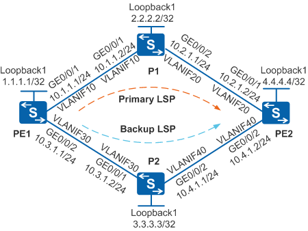
As shown in Figure 1, the network topology is simple and stable. PEs and P are MPLS backbone network devices, and LDP LSPs are set up on the backbone network to transmit network services.
Network services, such as VoIP, online game, and online video service, have high requirements for real-timeness. Data loss caused by faulty links will seriously affect services. It is required that services be fast switched to the backup LSP when the primary LSP becomes faulty, minimizing packet loss. Static BFD for LDP LSPs is configured to fast detect LDP LSPs.

In this scenario, to avoid loops, ensure that all connected interfaces have STP disabled and connected interfaces are removed from VLAN 1. If STP is enabled and VLANIF interfaces of switches are used to construct a Layer 3 ring network, an interface on the network will be blocked. As a result, Layer 3 services on the network cannot run normally.
Configuration Roadmap
The configuration roadmap is as follows:
- Configure OSPF between the PEs and P to implement IP connectivity on the backbone network.
- Configure local LDP sessions on PEs and P so that LDP LSPs can be set up to transmit network services.
- Configure static BFD on PEs to fast detect LDP LSPs.
Procedure
- Create VLANs and VLANIF interfaces on the switch, configure IP addresses
for the VLANIF interfaces, and add physical interfaces to the VLANs.
# Configure PE1. The configurations of P1, P2, and PE2 are similar to the configuration of PE1, and are not mentioned here.
<HUAWEI> system-view
[HUAWEI] sysname PE1
[PE1] interface loopback 1
[PE1-LoopBack1] ip address 1.1.1.1 32
[PE1-LoopBack1] quit
[PE1] vlan batch 10 30
[PE1] interface vlanif 10
[PE1-Vlanif10] ip address 10.1.1.1 24
[PE1-Vlanif10] quit
[PE1] interface vlanif 30
[PE1-Vlanif30] ip address 10.3.1.1 24
[PE1-Vlanif30] quit
[PE1] interface gigabitethernet 0/0/1
[PE1-GigabitEthernet0/0/1] port link-type trunk
[PE1-GigabitEthernet0/0/1] port trunk allow-pass vlan 10
[PE1-GigabitEthernet0/0/1] quit
[PE1] interface gigabitethernet 0/0/2
[PE1-GigabitEthernet0/0/2] port link-type trunk
[PE1-GigabitEthernet0/0/2] port trunk allow-pass vlan 30
[PE1-GigabitEthernet0/0/2] quit
- Configure OSPF to advertise the network segments connecting
to interfaces on each node and to advertise the routes of hosts with
LSR IDs.
# Configure PE1. The configurations of P1, P2, and PE2 are similar to the configuration of PE1, and are not mentioned here.
[PE1] ospf 1
[PE1-ospf-1] area 0
[PE1-ospf-1-area-0.0.0.0] network 1.1.1.1 0.0.0.0
[PE1-ospf-1-area-0.0.0.0] network 10.1.1.0 0.0.0.255
[PE1-ospf-1-area-0.0.0.0] network 10.3.1.0 0.0.0.255
[PE1-ospf-1-area-0.0.0.0] quit
[PE1-ospf-1] quit
- Set the cost of VLANIF 30 on PE1 to 1000.
[PE1] interface vlanif 30
[PE1-Vlanif30] ospf cost 1000
[PE1-Vlanif30] quit
After the configuration is complete, run the display ip routing-table command on each node. You can see that the nodes learn routes from each other. The outbound interface of the route from PE1 to PE2 is VLANIF 10.
- Configure local LDP sessions.
# Configure PE1. The configurations of P1, P2, and PE2 are similar to the configuration of PE1, and are not mentioned here.
[PE1] mpls lsr-id 1.1.1.1
[PE1] mpls
[PE1-mpls] quit
[PE1] mpls ldp
[PE1-mpls-ldp] quit
[PE1] interface vlanif 10
[PE1-Vlanif10] mpls
[PE1-Vlanif10] mpls ldp
[PE1-Vlanif10] quit
[PE1] interface vlanif 30
[PE1-Vlanif30] mpls
[PE1-Vlanif30] mpls ldp
[PE1-Vlanif30] quit
# Run the display mpls ldp lsp command. The command output shows that an LDP LSP destined for 4.4.4.4/32 is set up on PE1.
[PE1] display mpls ldp lsp LDP LSP Information ------------------------------------------------------------------------------- Flag after Out IF: (I) - LSP Is Only Iterated by RLFA ------------------------------------------------------------------------------- DestAddress/Mask In/OutLabel UpstreamPeer NextHop OutInterface ------------------------------------------------------------------------------- 1.1.1.1/32 3/NULL 2.2.2.2 127.0.0.1 InLoop0 1.1.1.1/32 3/NULL 3.3.3.3 127.0.0.1 InLoop0 *1.1.1.1/32 Liberal/1024 DS/2.2.2.2 *1.1.1.1/32 Liberal/1024 DS/3.3.3.3 2.2.2.2/32 NULL/3 - 10.1.1.2 Vlanif10 2.2.2.2/32 1024/3 2.2.2.2 10.1.1.2 Vlanif10 2.2.2.2/32 1024/3 3.3.3.3 10.1.1.2 Vlanif10 *2.2.2.2/32 Liberal/1025 DS/3.3.3.3 3.3.3.3/32 NULL/1026 - 10.1.1.2 Vlanif10 3.3.3.3/32 1026/1026 2.2.2.2 10.1.1.2 Vlanif10 3.3.3.3/32 1026/1026 3.3.3.3 10.1.1.2 Vlanif10 *3.3.3.3/32 Liberal/3 DS/3.3.3.3 4.4.4.4/32 NULL/1025 - 10.1.1.2 Vlanif10 4.4.4.4/32 1025/1025 2.2.2.2 10.1.1.2 Vlanif10 4.4.4.4/32 1025/1025 3.3.3.3 10.1.1.2 Vlanif10 *4.4.4.4/32 Liberal/1026 DS/3.3.3.3 ------------------------------------------------------------------------------- TOTAL: 11 Normal LSP(s) Found. TOTAL: 5 Liberal LSP(s) Found. TOTAL: 0 Frr LSP(s) Found. A '*' before an LSP means the LSP is not established A '*' before a Label means the USCB or DSCB is stale A '*' before a UpstreamPeer means the session is stale A '*' before a DS means the session is stale A '*' before a NextHop means the LSP is FRR LSP - Enable global BFD on the two nodes of the detected link.
# Configure PE1.
[PE1] bfd
[PE1-bfd] quit
# Configure PE2.
[PE2] bfd
[PE2-bfd] quit
- Bind the BFD session destined for the LDP LSP on PE1. Set
the interval for sending and receiving packets to both 100 ms. Configure
the port status table to be changeable.
# Configure PE1.
[PE1] bfd pe1tope2 bind ldp-lsp peer-ip 4.4.4.4 nexthop 10.1.1.2 interface vlanif 10 [PE1-bfd-lsp-session-pe1tope2] discriminator local 1 [PE1-bfd-lsp-session-pe1tope2] discriminator remote 2 [PE1-bfd-lsp-session-pe1tope2] min-tx-interval 100 [PE1-bfd-lsp-session-pe1tope2] min-rx-interval 100 [PE1-bfd-lsp-session-pe1tope2] process-pst [PE1-bfd-lsp-session-pe1tope2] commit [PE1-bfd-lsp-session-pe1tope2] quit - On PE2, configure a BFD session that is bound to the IP
link to notify PE1 of the detected faults on the LDP LSP.
# Configure PE2.
[PE2] bfd pe2tope1 bind peer-ip 1.1.1.1
[PE2-bfd-session-pe2tope1] discriminator local 2
[PE2-bfd-session-pe2tope1] discriminator remote 1
[PE2-bfd-session-pe2tope1] min-tx-interval 100
[PE2-bfd-session-pe2tope1] min-rx-interval 100
[PE2-bfd-session-pe2tope1] commit
[PE2-bfd-session-pe2tope1] quit
- Verify the configuration.
# Run the display bfd session all command on PE1. The command output shows that the State field is displayed as Up.
[PE1] display bfd session all
--------------------------------------------------------------------------------
Local Remote     PeerIpAddr      State     Type        InterfaceName
--------------------------------------------------------------------------------
1     2          4.4.4.4         Up        S_LDP_LSP   Vlanif10
--------------------------------------------------------------------------------
     Total UP/DOWN Session Number : 1/0
# Run the display bfd session all command on PE2, and the command output that the State field is displayed as Up.
[PE2] display bfd session all
--------------------------------------------------------------------------------
Local Remote     PeerIpAddr      State     Type        InterfaceName
--------------------------------------------------------------------------------
2     1          1.1.1.1         Up        S_IP_PEER         -
--------------------------------------------------------------------------------
     Total UP/DOWN Session Number : 1/0
Configuration Files
PE1 configuration file
#
sysname PE1
#
vlan batch 10 30
#
bfd
#
mpls lsr-id 1.1.1.1
mpls
#
mpls ldp
#
interface Vlanif10
 ip address 10.1.1.1 255.255.255.0
 mpls
 mpls ldp
#
interface Vlanif30
 ip address 10.3.1.1 255.255.255.0
 ospf cost 1000
 mpls
 mpls ldp
#
interface GigabitEthernet0/0/1
 port link-type trunk
 port trunk allow-pass vlan 10
#
interface GigabitEthernet0/0/2
 port link-type trunk
 port trunk allow-pass vlan 30
#
interface LoopBack1
 ip address 1.1.1.1 255.255.255.255
#
ospf 1
 area 0.0.0.0
  network 1.1.1.1 0.0.0.0
  network 10.1.1.0 0.0.0.255
  network 10.3.1.0 0.0.0.255
#
bfd pe1tope2 bind ldp-lsp peer-ip 4.4.4.4 nexthop 10.1.1.2 interface Vlanif10
 discriminator local 1
 discriminator remote 2
 min-tx-interval 100
 min-rx-interval 100
 process-pst
 commit
#
return
P1 configuration file
#
sysname P1
#
vlan batch 10 20
#
mpls lsr-id 2.2.2.2
mpls
#
mpls ldp
#
interface Vlanif10
 ip address 10.1.1.2 255.255.255.0
 mpls
 mpls ldp
#
interface Vlanif20
 ip address 10.2.1.1 255.255.255.0
 mpls
 mpls ldp
#
interface GigabitEthernet0/0/1
 port link-type trunk
 port trunk allow-pass vlan 10
#
interface GigabitEthernet0/0/2
 port link-type trunk
 port trunk allow-pass vlan 20
#
interface LoopBack1
 ip address 2.2.2.2 255.255.255.255
#
ospf 1
 area 0.0.0.0
  network 2.2.2.2 0.0.0.0
  network 10.1.1.0 0.0.0.255
  network 10.2.1.0 0.0.0.255
#
return
P2 configuration file
#
sysname P2
#
vlan batch 30 40
#
mpls lsr-id 3.3.3.3
mpls
#
mpls ldp
#
interface Vlanif30
 ip address 10.3.1.2 255.255.255.0
 mpls
 mpls ldp
#
interface Vlanif40
 ip address 10.4.1.1 255.255.255.0
 mpls
 mpls ldp
#
interface GigabitEthernet0/0/1
 port link-type trunk
 port trunk allow-pass vlan 30
#
interface GigabitEthernet0/0/2
 port link-type trunk
 port trunk allow-pass vlan 40
#
interface LoopBack1
 ip address 3.3.3.3 255.255.255.255
#
ospf 1
 area 0.0.0.0
  network 3.3.3.3 0.0.0.0
  network 10.3.1.0 0.0.0.255
  network 10.4.1.0 0.0.0.255
#
return
PE2 configuration file
#
sysname PE2
#
vlan batch 20 40
#
bfd
#
mpls lsr-id 4.4.4.4
mpls
#
mpls ldp
#
interface Vlanif20
 ip address 10.2.1.2 255.255.255.0
 mpls
 mpls ldp
#
interface Vlanif40
 ip address 10.4.1.2 255.255.255.0
 mpls
 mpls ldp
#
interface GigabitEthernet0/0/1
 port link-type trunk
 port trunk allow-pass vlan 20
#
interface GigabitEthernet0/0/2
 port link-type trunk
 port trunk allow-pass vlan 40
#
interface LoopBack1
 ip address 4.4.4.4 255.255.255.255
#
bfd pe2tope1 bind peer-ip 1.1.1.1
 discriminator local 2
 discriminator remote 1
 min-tx-interval 100
 min-rx-interval 100
 commit
#
ospf 1
 area 0.0.0.0
  network 4.4.4.4 0.0.0.0
  network 10.2.1.0 0.0.0.255
  network 10.4.1.0 0.0.0.255
#
return