Example for Configuring Coexistent Local and Remote LDP Session
Networking Requirements
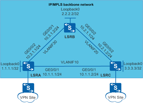
In Figure 1, LSRA and LSRC are provider edge (PE) devices on the Internet Protocol/Multiprotocol Label Switching (IP/MPLS) backbone network. MPLS Layer 2 virtual private network (L2VPN) needs to be configured on LSRA and LSRC to enable communication between VPN sites. A local Label Distribution Protocol (LDP) session can be configured between the LSRs to establish an LDP label switched path (LSP) for transmitting the VPN service. In addition, a remote LDP session can be configured between LSRA and LSRC to implement coexistent local and remote LDP session.

In this scenario, to avoid loops, ensure that all connected interfaces have STP disabled and connected interfaces are removed from VLAN 1. If STP is enabled and VLANIF interfaces of switches are used to construct a Layer 3 ring network, an interface on the network will be blocked. As a result, Layer 3 services on the network cannot run normally.
Configuration Roadmap
The configuration roadmap is as follows:
- Configure Open Shortest Path First (OSPF) on the LSRs to ensure IP connectivity on the backbone network.
- Configure a local LDP session between the LSRs to transmit the VPN service over a public network tunnel.
- Configure a remote LDP session between LSRA and LSRC to improve the L2VPN service reliability.
Procedure
- Create VLANs and VLANIF interfaces on each switch, configure IP addresses for the VLANIF interfaces, and add physical interfaces to VLANs.
# Configure LSRA. The configurations on LSRB and LSRC are similar to the configuration on LSRA, and are not mentioned here.
<HUAWEI> system-view
[HUAWEI] sysname LSRA
[LSRA] interface loopback 0
[LSRA-LoopBack0] ip address 1.1.1.1 32
[LSRA-LoopBack0] quit
[LSRA] vlan batch 10 30
[LSRA] interface vlanif 10
[LSRA-Vlanif10] ip address 10.1.1.1 24
[LSRA-Vlanif10] quit
[LSRA] interface gigabitethernet 0/0/1
[LSRA-GigabitEthernet0/0/1] port link-type trunk
[LSRA-GigabitEthernet0/0/1] port trunk allow-pass vlan 10
[LSRA-GigabitEthernet0/0/1] quit
[LSRA] interface vlanif 30
[LSRA-Vlanif30] ip address 10.3.1.1 24
[LSRA-Vlanif30] quit
[LSRA] interface gigabitethernet 0/0/2
[LSRA-GigabitEthernet0/0/2] port link-type trunk
[LSRA-GigabitEthernet0/0/2] port trunk allow-pass vlan 30
[LSRA-GigabitEthernet0/0/2] quit
- Configure OSPF to advertise the network segments that the interfaces are connected to and the host route of the LSR ID.
# Configure LSRA.
[LSRA] ospf 1
[LSRA-ospf-1] area 0
[LSRA-ospf-1-area-0.0.0.0] network 1.1.1.1 0.0.0.0
[LSRA-ospf-1-area-0.0.0.0] network 10.1.1.0 0.0.0.255
[LSRA-ospf-1-area-0.0.0.0] network 10.3.1.0 0.0.0.255
[LSRA-ospf-1-area-0.0.0.0] quit
[LSRA-ospf-1] quit
# Configure LSRB.
[LSRB] ospf 1
[LSRB-ospf-1] area 0
[LSRB-ospf-1-area-0.0.0.0] network 2.2.2.2 0.0.0.0
[LSRB-ospf-1-area-0.0.0.0] network 10.3.1.0 0.0.0.255
[LSRB-ospf-1-area-0.0.0.0] network 10.2.1.0 0.0.0.255
[LSRB-ospf-1-area-0.0.0.0] quit
[LSRB-ospf-1] quit
# Configure LSRC.
[LSRC] ospf 1
[LSRC-ospf-1] area 0
[LSRC-ospf-1-area-0.0.0.0] network 3.3.3.3 0.0.0.0
[LSRC-ospf-1-area-0.0.0.0] network 10.1.1.0 0.0.0.255
[LSRC-ospf-1-area-0.0.0.0] network 10.2.1.0 0.0.0.255
[LSRC-ospf-1-area-0.0.0.0] quit
[LSRC-ospf-1] quit
# After the configuration is complete, run the display ip routing-table command on each node. You can see that nodes learn routes from each other.
- Enable MPLS and MPLS LDP globally on each LSR.
# Configure LSRA.
[LSRA] mpls lsr-id 1.1.1.1
[LSRA] mpls
[LSRA-mpls] quit
[LSRA] mpls ldp
[LSRA-mpls-ldp] quit
# Configure LSRB.
[LSRB] mpls lsr-id 2.2.2.2
[LSRB] mpls
[LSRB-mpls] quit
[LSRB] mpls ldp
[LSRB-mpls-ldp] quit
# Configure LSRC.
[LSRC] mpls lsr-id 3.3.3.3
[LSRC] mpls
[LSRC-mpls] quit
[LSRC] mpls ldp
[LSRC-mpls-ldp] quit
- Enable MPLS and MPLS LDP on VLANIF interfaces of each LSR.
# Configure LSRA.
[LSRA] interface vlanif 10
[LSRA-Vlanif10] mpls
[LSRA-Vlanif10] mpls ldp
[LSRA-Vlanif10] quit
[LSRA] interface vlanif 30
[LSRA-Vlanif30] mpls
[LSRA-Vlanif30] mpls ldp
[LSRA-Vlanif30] quit
# Configure LSRB.
[LSRB] interface vlanif 30
[LSRB-Vlanif30] mpls
[LSRB-Vlanif30] mpls ldp
[LSRB-Vlanif30] quit
[LSRB] interface vlanif 20
[LSRB-Vlanif20] mpls
[LSRB-Vlanif20] mpls ldp
[LSRB-Vlanif20] quit
# Configure LSRC.
[LSRC] interface vlanif 10
[LSRC-Vlanif10] mpls
[LSRC-Vlanif10] mpls ldp
[LSRC-Vlanif10] quit
[LSRC] interface vlanif 20
[LSRC-Vlanif20] mpls
[LSRC-Vlanif20] mpls ldp
[LSRC-Vlanif20] quit
- Specify a remote peer and its IP address on LSRA and LSRC.
# Configure LSRA.
[LSRA] mpls ldp remote-peer LSRC
[LSRA-mpls-ldp-remote-lsrc] remote-ip 3.3.3.3
[LSRA-mpls-ldp-remote-lsrc] quit
# Configure LSRC.
[LSRC] mpls ldp remote-peer LSRA
[LSRC-mpls-ldp-remote-lsra] remote-ip 1.1.1.1
[LSRC-mpls-ldp-remote-lsra] quit
- Disable STP on each LSR.
# Configure LSRA. The configurations on LSRB and LSRC are similar to the configuration on LSRA, and are not mentioned here.
<LSRA> system-view [HUAWEI] stp disable - Verify the configuration.
# After the configuration is complete, run the display mpls ldp adjacency command on LSRA and LSRC. You can see that both a local adjacency and a remote adjacency are established between LSRA and LSRC.
The command output on LSRA is provided as an example:
[LSRA] display mpls ldp adjacency
LDP Adjacency Information in Public Network
 Codes: R: Remote Adjacency, L: Local Adjacency
 A '*' before an adjacency means the adjacency is being deleted.
 ------------------------------------------------------------------------------
 SN    SourceAddr      PeerID          VrfID AdjAge(DDDD:HH:MM) RcvdHello Type
 ------------------------------------------------------------------------------
  1    10.1.1.2        3.3.3.3         0     0000:00:16         195       L
  2    10.3.1.2        2.2.2.2         0     0000:00:03         40        L
  3    3.3.3.3         3.3.3.3         0     0000:00:03         18        R
 ------------------------------------------------------------------------------
 TOTAL: 3 Record(s) found.
# Run the display mpls ldp session statistics command on LSRA and LSRC. You can see that a coexistent local and remote LDP session is displayed on LSRA and LSRC.
The command output on LSRA is provided as an example:
[LSRA] display mpls ldp session statistics
 LDP Session Statistics Information
 ------------------------------------------------------------
 SessionType         Local   Remote   Local&Remote   Total
 ------------------------------------------------------------
 Not Operational     0       0        0              0
 Operational         1       0        1              2
 ------------------------------------------------------------
 SessionStatistics   1       0        1              2
 ------------------------------------------------------------
Run the display mpls ldp lsp command on LSRA. You can see that the outbound interface on the LSP between LSRA and LSRC is VLANIF 10.
[LSRA] display mpls ldp lsp

 LDP LSP Information
 -------------------------------------------------------------------------------
 Flag after Out IF: (I) - LSP Is Only Iterated by RLFA
 -------------------------------------------------------------------------------
 DestAddress/Mask   In/OutLabel    UpstreamPeer    NextHop         OutInterface
 -------------------------------------------------------------------------------

 1.1.1.1/32         3/NULL         3.3.3.3         127.0.0.1       InLoop0
 1.1.1.1/32         3/NULL         2.2.2.2         127.0.0.1       InLoop0
*1.1.1.1/32         Liberal/1025                   DS/3.3.3.3
*1.1.1.1/32         Liberal/1025                   DS/2.2.2.2
 2.2.2.2/32         NULL/3         -               10.3.1.2        Vlanif30
 2.2.2.2/32         1025/3         2.2.2.2         10.3.1.2        Vlanif30
 2.2.2.2/32         1025/3         3.3.3.3         10.3.1.2        Vlanif30
*2.2.2.2/32         Liberal/1024                   DS/3.3.3.3
 3.3.3.3/32         NULL/3         -               10.1.1.2        Vlanif10
 3.3.3.3/32         1024/3         3.3.3.3         10.1.1.2        Vlanif10
 3.3.3.3/32         1024/3         2.2.2.2         10.1.1.2        Vlanif10
*3.3.3.3/32         Liberal/1024                   DS/2.2.2.2
 -------------------------------------------------------------------------------
 TOTAL: 8 Normal LSP(s) Found.
 TOTAL: 4 Liberal LSP(s) Found.
 TOTAL: 0 Frr LSP(s) Found.
 A '*' before an LSP means the LSP is not established
 A '*' before a Label means the USCB or DSCB is stale
 A '*' before a UpstreamPeer means the session is stale
 A '*' before a DS means the session is stale
 A '*' before a NextHop means the LSP is FRR LSP
After you shut down GigabitEthernet0/0/1 on LSRA, the directly connected physical link between LSRA and LSRC fails. The local adjacency between LSRA and LSRC goes Down, but they are still reachable through LSRB. The remote adjacency remains Up, the session type changes to remote. Since the session is still Up, L2VPN is unaware of the session type change and does not delete the session. This avoids the neighbor disconnection and recovery process and therefore reduces the service interruption time.
The command output on LSRA is provided as an example:
[LSRA] display mpls ldp adjacency
LDP Adjacency Information in Public Network
 Codes: R: Remote Adjacency, L: Local Adjacency
 A '*' before an adjacency means the adjacency is being deleted.
 ------------------------------------------------------------------------------
 SN    SourceAddr      PeerID          VrfID AdjAge(DDDD:HH:MM) RcvdHello Type
 ------------------------------------------------------------------------------
  1    10.3.1.2        2.2.2.2         0     0000:00:03         43        L
  2    3.3.3.3         3.3.3.3         0     0000:00:02         11        R
 ------------------------------------------------------------------------------
 TOTAL: 2 Record(s) found.
[LSRA] display mpls ldp session statistics
LDP Session Statistics Information
 ------------------------------------------------------------
 SessionType         Local   Remote   Local&Remote   Total
 ------------------------------------------------------------
 Not Operational     0       0        0              0
 Operational         1       1        0              2
 ------------------------------------------------------------
 SessionStatistics   1       1        0              2
 ------------------------------------------------------------
Run the display mpls ldp lsp command on LSRA again. You can see that the outbound interface on the LSP between LSRA and LSRC changes to VLANIF 30.
[LSRA] display mpls ldp lsp

 LDP LSP Information
 -------------------------------------------------------------------------------
 Flag after Out IF: (I) - LSP Is Only Iterated by RLFA
 -------------------------------------------------------------------------------
 DestAddress/Mask   In/OutLabel    UpstreamPeer    NextHop         OutInterface
 -------------------------------------------------------------------------------

 1.1.1.1/32         3/NULL         3.3.3.3         127.0.0.1       InLoop0
 1.1.1.1/32         3/NULL         2.2.2.2         127.0.0.1       InLoop0
*1.1.1.1/32         Liberal/1025                   DS/3.3.3.3
*1.1.1.1/32         Liberal/1025                   DS/2.2.2.2
 2.2.2.2/32         NULL/3         -               10.3.1.2        Vlanif30
 2.2.2.2/32         1025/3         2.2.2.2         10.3.1.2        Vlanif30
 2.2.2.2/32         1025/3         3.3.3.3         10.3.1.2        Vlanif30
*2.2.2.2/32         Liberal/1024                   DS/3.3.3.3
 3.3.3.3/32         NULL/1024      -               10.3.1.2        Vlanif30
 3.3.3.3/32         1024/1024      3.3.3.3         10.3.1.2        Vlanif30
 3.3.3.3/32         1024/1024      2.2.2.2         10.3.1.2        Vlanif30
*3.3.3.3/32         Liberal/3                      DS/3.3.3.3
 -------------------------------------------------------------------------------
 TOTAL: 8 Normal LSP(s) Found.
 TOTAL: 4 Liberal LSP(s) Found.
 TOTAL: 0 Frr LSP(s) Found.
 A '*' before an LSP means the LSP is not established
 A '*' before a Label means the USCB or DSCB is stale
 A '*' before a UpstreamPeer means the session is stale
 A '*' before a DS means the session is stale
 A '*' before a NextHop means the LSP is FRR LSP
After you run the undo shutdown command to enable GigabitEthernet0/0/1 on LSRA, the directly connected physical link between LSRA and LSRC recovers. The L2VPN service will automatically switch back to the shortest path (local adjacency). Run the display mpls ldp lsp command on LSRA. You can see that the outbound interface on the LSP between LSRA and LSRC changes to VLANIF 10.
[LSRA] display mpls ldp lsp

 LDP LSP Information
 -------------------------------------------------------------------------------
 Flag after Out IF: (I) - LSP Is Only Iterated by RLFA
 -------------------------------------------------------------------------------
 DestAddress/Mask   In/OutLabel    UpstreamPeer    NextHop         OutInterface
 -------------------------------------------------------------------------------

 1.1.1.1/32         3/NULL         3.3.3.3         127.0.0.1       InLoop0
 1.1.1.1/32         3/NULL         2.2.2.2         127.0.0.1       InLoop0
*1.1.1.1/32         Liberal/1025                   DS/3.3.3.3
*1.1.1.1/32         Liberal/1025                   DS/2.2.2.2
 2.2.2.2/32         NULL/3         -               10.3.1.2        Vlanif30
 2.2.2.2/32         1025/3         2.2.2.2         10.3.1.2        Vlanif30
 2.2.2.2/32         1025/3         3.3.3.3         10.3.1.2        Vlanif30
*2.2.2.2/32         Liberal/1024                   DS/3.3.3.3
 3.3.3.3/32         NULL/3         -               10.1.1.2        Vlanif10
 3.3.3.3/32         1024/3         3.3.3.3         10.1.1.2        Vlanif10
 3.3.3.3/32         1024/3         2.2.2.2         10.1.1.2        Vlanif10
*3.3.3.3/32         Liberal/1024                   DS/2.2.2.2
 -------------------------------------------------------------------------------
 TOTAL: 8 Normal LSP(s) Found.
 TOTAL: 4 Liberal LSP(s) Found.
 TOTAL: 0 Frr LSP(s) Found.
 A '*' before an LSP means the LSP is not established
 A '*' before a Label means the USCB or DSCB is stale
 A '*' before a UpstreamPeer means the session is stale
 A '*' before a DS means the session is stale
 A '*' before a NextHop means the LSP is FRR LSP
Configuration Files
LSRA configuration file
#
sysname LSRA
#
vlan batch 10 30
#
stp disable
#
mpls lsr-id 1.1.1.1
mpls
#
mpls ldp
#
mpls ldp remote-peer lsrc
 remote-ip 3.3.3.3
#
interface Vlanif10
 ip address 10.1.1.1 255.255.255.0
 mpls
 mpls ldp
#
interface Vlanif30
 ip address 10.3.1.1 255.255.255.0
 mpls
 mpls ldp
#
interface GigabitEthernet0/0/1
 port link-type trunk
 port trunk allow-pass vlan 10
#
interface GigabitEthernet0/0/2
 port link-type trunk
 port trunk allow-pass vlan 30
#
interface LoopBack0
 ip address 1.1.1.1 255.255.255.255
#
ospf 1
 area 0.0.0.0
  network 1.1.1.1 0.0.0.0
  network 10.3.1.0 0.0.0.255
  network 10.1.1.0 0.0.0.255
#
return
LSRB configuration file
#
sysname LSRB
#
vlan batch 20 30
#
stp disable
#
mpls lsr-id 2.2.2.2
mpls
#
mpls ldp
#
interface Vlanif20
 ip address 10.2.1.1 255.255.255.0
 mpls
 mpls ldp
#
interface Vlanif30
 ip address 10.3.1.2 255.255.255.0
 mpls
 mpls ldp
#
interface GigabitEthernet0/0/1
 port link-type trunk
 port trunk allow-pass vlan 30
#
interface GigabitEthernet0/0/2
 port link-type trunk
 port trunk allow-pass vlan 20
#
interface LoopBack0
 ip address 2.2.2.2 255.255.255.255
#
ospf 1
 area 0.0.0.0
  network 2.2.2.2 0.0.0.0
  network 10.3.1.0 0.0.0.255
  network 10.2.1.0 0.0.0.255
#
return
LSRC configuration file
#
sysname LSRC
#
vlan batch 10 20
#
stp disable
#
mpls lsr-id 3.3.3.3
mpls
#
mpls ldp
#
mpls ldp remote-peer lsra
 remote-ip 1.1.1.1
#
interface Vlanif10
 ip address 10.1.1.2 255.255.255.0
 mpls
 mpls ldp
#
interface Vlanif20
 ip address 10.2.1.2 255.255.255.0
 mpls
 mpls ldp
#
interface GigabitEthernet0/0/1
 port link-type trunk
 port trunk allow-pass vlan 10
#
interface GigabitEthernet0/0/2
 port link-type trunk
 port trunk allow-pass vlan 20
#
interface LoopBack0
 ip address 3.3.3.3 255.255.255.255
#
ospf 1
 area 0.0.0.0
  network 3.3.3.3 0.0.0.0
  network 10.1.1.0 0.0.0.255
  network 10.2.1.0 0.0.0.255
#
return