Example for Configuring RSVP Authentication
Networking Requirements
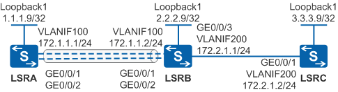
As shown in Figure 1, VLANIF100 between LSRA and LSRB contains member interfaces GE0/0/1 and GE0/0/2. An MPLS TE tunnel from LSRA to LSRC is set up by using RSVP.
The handshake function needs to be configured so that LSRA and LSRB perform RSPV authentication to prevent forged Resv messages from consuming network resources. In addition, the message window function is configured to solve the problem of RSVP packet mis-sequencing.
Configuration Roadmap
The configuration roadmap is as follows:
Assign an IP address to each interface on each LSR and configure OSPF to ensure that there are reachable routes between LSRs.
Configure an ID for each LSR and globally enable MPLS, MPLS TE, and RSVP-TE on each node and interface.
On the ingress node, create a tunnel interface, and specify the IP address, tunneling protocol, destination IP address, tunnel ID, and dynamic signaling protocol RSVP-TE, and enable CSPF.
Configure RSVP authentication on LSRA and LSRB of the tunnel.
Configure the Handshake function on LSRA and LSRB to prevent forged Resv messages from consuming network resources.
Configure the sliding window function on LSRA and LSRB to solve the problem of RSVP packet mis-sequencing.

It is recommended that the window size be larger than 32. If the window size is too small, some received RSVP messages may be discarded, which can terminate the RSVP neighbor relationships.
Procedure
- Assign an IP address to each interface and configure OSPF.
# Configure LSRA. Configure IP addresses for interfaces of LSRB and LSRC according to Figure 1. The configurations of LSRB and LSRC are similar to the configuration of LSRA, and are not mentioned here.
<HUAWEI> system-view
[HUAWEI] sysname LSRA
[LSRA] vlan batch 100
[LSRA] interface vlanif 100
[LSRA-Vlanif100] ip address 172.1.1.1 255.255.255.0
[LSRA-Vlanif100] quit
[LSRA] interface gigabitethernet 0/0/1
[LSRA-GigabitEthernet0/0/1] port link-type trunk
[LSRA-GigabitEthernet0/0/1] port trunk allow-pass vlan 100
[LSRA-GigabitEthernet0/0/1] quit
[LSRA] interface gigabitethernet 0/0/2
[LSRA-GigabitEthernet0/0/2] port link-type trunk
[LSRA-GigabitEthernet0/0/2] port trunk allow-pass vlan 100
[LSRA-GigabitEthernet0/0/2] quit
[LSRA] interface loopback 1
[LSRA-LoopBack1] ip address 1.1.1.9 255.255.255.255
[LSRA-LoopBack1] quit
[LSRA] ospf 1
[LSRA-ospf-1] area 0
[LSRA-ospf-1-area-0.0.0.0] network 1.1.1.9 0.0.0.0
[LSRA-ospf-1-area-0.0.0.0] network 172.1.1.0 0.0.0.255
[LSRA-ospf-1-area-0.0.0.0] quit
[LSRA-ospf-1] quit
After the configurations are complete, run the display ip routing-table command on each LSR. You can see that the LSRs have learned the routes to Loopback1 interfaces of each other.
- Configure basic MPLS functions and enable MPLS TE, RSVP-TE,
and CSPF.
# Configure LSRA. The configurations of LSRB and LSRC are similar to the configuration of LSRA, and are not mentioned here. CSPF only needs to be configured on the ingress node of the primary tunnel.
[LSRA] mpls lsr-id 1.1.1.9
[LSRA] mpls
[LSRA-mpls] mpls te
[LSRA-mpls] mpls rsvp-te
[LSRA-mpls] mpls te cspf
[LSRA-mpls] quit
[LSRA] interface vlanif 100
[LSRA-Vlanif100] mpls
[LSRA-Vlanif100] mpls te
[LSRA-Vlanif100] mpls rsvp-te
[LSRA-Vlanif100] quit
- Configure OSPF TE.
# Configure LSRA. The configurations of LSRB and LSRC are similar to the configuration of LSRA, and are not mentioned here.
[LSRA] ospf
[LSRA-ospf-1] opaque-capability enable
[LSRA-ospf-1] area 0
[LSRA-ospf-1-area-0.0.0.0] mpls-te enable
[LSRA-ospf-1-area-0.0.0.0] quit
[LSRA-ospf-1] quit
- Create an MPLS TE tunnel on the ingress node.
# Create Tunnel1 on LSRA.
[LSRA] interface tunnel 1
[LSRA-Tunnel1] ip address unnumbered interface loopback 1
[LSRA-Tunnel1] tunnel-protocol mpls te
[LSRA-Tunnel1] destination 3.3.3.9
[LSRA-Tunnel1] mpls te tunnel-id 101
[LSRA-Tunnel1] mpls te commit
[LSRA-Tunnel1] quit
After the configurations are complete, run the display interface tunnel command on LSRA. You can see that the tunnel interface status is Up.
[LSRA] display interface tunnel 1
Tunnel1 current state : UP
Line protocol current state : UP
Last line protocol up time : 2013-02-22 14:28:37
Description:...
- On LSRA and LSRB, configure RSVP authentication on the
interfaces on the MPLS TE link.
# Configure LSRA.
[LSRA] interface vlanif 100
[LSRA-Vlanif100] mpls rsvp-te authentication cipher Huawei@1234
[LSRA-Vlanif100] mpls rsvp-te authentication handshake
[LSRA-Vlanif100] mpls rsvp-te authentication window-size 32
[LSRA-Vlanif100] quit
# Configure LSRB.
[LSRB] interface vlanif 100
[LSRB-Vlanif100] mpls rsvp-te authentication cipher Huawei@1234
[LSRB-Vlanif100] mpls rsvp-te authentication handshake
[LSRB-Vlanif100] mpls rsvp-te authentication window-size 32
[LSRB-Vlanif100] quit
- Verify the configuration.
Run the reset mpls rsvp-te command, and then run the display interface tunnel command on LSRA. You can see that the tunnel interface is Up.
Run the display mpls rsvp-te interface command on LSRA or LSRB to view information about RSVP authentication.
[LSRA] display mpls rsvp-te interface vlanif 100
Interface: Vlanif100
 Interface Address: 172.1.1.1
 Interface state: UP                   Interface Index: 0x36
 Total-BW: 0                           Used-BW: 0
 Hello configured: NO                  Num of Neighbors: 1
 SRefresh feature: DISABLE             SRefresh Interval: 30 sec
 Mpls Mtu: 1500                        Retransmit Interval: 5000 msec
 Increment Value: 1                    Authentication: ENABLE
 Challenge: ENABLE                     WindowSize: 32
 Next Seq # to be sent:2767789282 0    Key ID: 0xa4ff1cdc0000
 Bfd Enabled: DISABLE                  Bfd Min-Tx: 1000
 Bfd Min-Rx: 1000                      Bfd Detect-Multi: 3
Configuration Files
LSRA configuration file
#
sysname LSRA
#
vlan batch 100
#
mpls lsr-id 1.1.1.9
mpls
 mpls te
 mpls rsvp-te
 mpls te cspf
#
interface Vlanif100
 ip address 172.1.1.1 255.255.255.0
 mpls
 mpls te
 mpls rsvp-te
 mpls rsvp-te authentication cipher %^%#P>Z{S["[&0D+~^McJ#GX~ij}D%N|y;w4*D;M!WJE%^%#
 mpls rsvp-te authentication handshake
 mpls rsvp-te authentication window-size 32
#
interface GigabitEthernet0/0/1
 port link-type trunk
 port trunk allow-pass vlan 100
#
interface GigabitEthernet0/0/2
 port link-type trunk
 port trunk allow-pass vlan 100
#
interface LoopBack1
 ip address 1.1.1.9 255.255.255.255
#
interface Tunnel1
 ip address unnumbered interface LoopBack1
 tunnel-protocol mpls te
 destination 3.3.3.9
 mpls te tunnel-id 101
 mpls te commit
#
ospf 1
 opaque-capability enable
 area 0.0.0.0
  network 1.1.1.9 0.0.0.0
  network 172.1.1.0 0.0.0.255
  mpls-te enable
#
return
LSRB configuration file
#
sysname LSRB
#
vlan batch 100 200
#
mpls lsr-id 2.2.2.9
mpls
 mpls te
 mpls rsvp-te
#
interface Vlanif100
 ip address 172.1.1.2 255.255.255.0
 mpls
 mpls te
 mpls rsvp-te
 mpls rsvp-te authentication cipher %^%#DbqR!4[#1)#D0,Gv*|(<^`B>1},"k2[QT}T)*C5+%^%#
 mpls rsvp-te authentication handshake
 mpls rsvp-te authentication window-size 32
#
interface Vlanif200
 ip address 172.2.1.1 255.255.255.0
 mpls
 mpls te
 mpls rsvp-te
#
interface GigabitEthernet0/0/1
 port link-type trunk
 port trunk allow-pass vlan 100
#
interface GigabitEthernet0/0/2
 port link-type trunk
 port trunk allow-pass vlan 100
#
interface GigabitEthernet0/0/3
 port link-type trunk
 port trunk allow-pass vlan 200
#
interface LoopBack1
 ip address 2.2.2.9 255.255.255.255
#
ospf 1
 opaque-capability enable
 area 0.0.0.0
  network 2.2.2.9 0.0.0.0
  network 172.1.1.0 0.0.0.255
  network 172.2.1.0 0.0.0.255
  mpls-te enable
#
return
LSRC configuration file
#
sysname LSRC
#
vlan batch 200
#
mpls lsr-id 3.3.3.9
mpls
 mpls te
 mpls rsvp-te
#
interface Vlanif200
 ip address 172.2.1.2 255.255.255.0
 mpls
 mpls te
 mpls rsvp-te
#
interface GigabitEthernet0/0/1
 port link-type trunk
 port trunk allow-pass vlan 200
#
interface LoopBack1
 ip address 3.3.3.9 255.255.255.255
#
ospf 1
 opaque-capability enable
 area 0.0.0.0
  network 3.3.3.9 0.0.0.0
  network 172.2.1.0 0.0.0.255
  mpls-te enable
#
return