Example for Configuring Association Between TE FRR and CR-LSP Backup
Networking Requirements
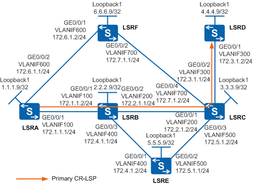
As shown in Figure 1, a primary tunnel is set up by using the explicit path LSRA -> LSRB -> LSRC -> LSRD. A bypass tunnel is set up on the transit node LSRB along the path LSRB -> LSRE -> LSRC; an ordinary backup CR-LSP is set up on the ingress node LSRA along the path LSRA -> LSRF -> LSRC -> LSRD.
When the link between LSRB and LSRC is faulty, the device starts the bypass tunnel (that is, the primary CR-LSP is in FRR-in-use state) and tries to restore the primary CR-LSP. At the same time, the system attempts to set up a backup CR-LSP.

In this scenario, to avoid loops, ensure that all connected interfaces have STP disabled and connected interfaces are removed from VLAN 1. If STP is enabled and VLANIF interfaces of switches are used to construct a Layer 3 ring network, an interface on the network will be blocked. As a result, Layer 3 services on the network cannot run normally.
Configuration Roadmap
The configuration roadmap is as follows:
Assign an IP address to each interface and configure OSPF to ensure that there are reachable routes between LSRs.
Configure an ID for each LSR and globally enable MPLS, MPLS TE, RSVP-TE, CSPF on each node and interface, and enable OSPF TE.
On the ingress node of the primary tunnel, create a tunnel interface, and specify the IP address, tunneling protocol, destination IP address, tunnel ID, and dynamic signaling protocol RSVP-TE for the tunnel interface.
Enable TE FRR on the interface of the primary tunnel on the ingress node.
On the ingress node LSRB, configure a bypass tunnel along the path LSRB -> LSRE -> LSRC to protect the link between LSRB and LSRC.
On the ingress node, set up an ordinary backup CR-LSP along the path LSRA -> LSRF -> LSRC -> LSRD.
On the ingress node, configure association between the bypass tunnel and the backup CR-LSP in the view of the interface of the primary tunnel.
Procedure
- Assign an IP address to each interface and configure OSPF.
# Configure LSRA. Configure IP addresses for interfaces on LSRB, LSRC, LSRD, LSRE, and LSRF according to Figure 1. The configurations of LSRB, LSRC, LSRD, LSRE, and LSRF are similar to the configuration of LSRA, and are not mentioned here.
<HUAWEI> system-view
[HUAWEI] sysname LSRA
[LSRA] vlan batch 100 600
[LSRA] interface vlanif 100
[LSRA-Vlanif100] ip address 172.1.1.1 255.255.255.0
[LSRA-Vlanif100] quit
[LSRA] interface vlanif 600
[LSRA-Vlanif600] ip address 172.6.1.1 255.255.255.0
[LSRA-Vlanif600] quit
[LSRA] interface gigabitethernet 0/0/1
[LSRA-GigabitEthernet0/0/1] port link-type trunk
[LSRA-GigabitEthernet0/0/1] port trunk allow-pass vlan 100
[LSRA-GigabitEthernet0/0/1] quit
[LSRA] interface gigabitethernet 0/0/2
[LSRA-GigabitEthernet0/0/2] port link-type trunk
[LSRA-GigabitEthernet0/0/2] port trunk allow-pass vlan 600
[LSRA-GigabitEthernet0/0/2] quit
[LSRA] interface loopback 1
[LSRA-LoopBack1] ip address 1.1.1.9 255.255.255.255
[LSRA-LoopBack1] quit
[LSRA] ospf 1
[LSRA-ospf-1] area 0
[LSRA-ospf-1-area-0.0.0.0] network 1.1.1.9 0.0.0.0
[LSRA-ospf-1-area-0.0.0.0] network 172.1.1.0 0.0.0.255
[LSRA-ospf-1-area-0.0.0.0] network 172.6.1.0 0.0.0.255
[LSRA-ospf-1-area-0.0.0.0] quit
[LSRA-ospf-1] quit
After the configurations are complete, run the display ip routing-table command on each LSR. You can see that the LSRs learn the routes to Loopback1 of each other. The display on LSRA is used as an example.
[LSRA] display ip routing-table Route Flags: R - relay, D - download to fib, T - to vpn-instance ------------------------------------------------------------------------------ Routing Tables: Public Destinations : 17 Routes : 21 Destination/Mask Proto Pre Cost Flags NextHop Interface 1.1.1.9/32 Direct 0 0 D 127.0.0.1 LoopBack1 2.2.2.9/32 OSPF 10 1 D 172.1.1.2 Vlanif100 3.3.3.9/32 OSPF 10 2 D 172.1.1.2 Vlanif100 OSPF 10 2 D 172.6.1.2 Vlanif600 4.4.4.9/32 OSPF 10 3 D 172.1.1.2 Vlanif100 OSPF 10 3 D 172.6.1.2 Vlanif600 5.5.5.9/32 OSPF 10 2 D 172.1.1.2 Vlanif100 6.6.6.9/32 OSPF 10 1 D 172.6.1.2 Vlanif600 127.0.0.0/8 Direct 0 0 D 127.0.0.1 InLoopBack0 127.0.0.1/32 Direct 0 0 D 127.0.0.1 InLoopBack0 172.1.1.0/24 Direct 0 0 D 172.1.1.1 Vlanif100 172.1.1.1/32 Direct 0 0 D 127.0.0.1 Vlanif100 172.2.1.0/24 OSPF 10 2 D 172.1.1.2 Vlanif100 172.3.1.0/24 OSPF 10 3 D 172.1.1.2 Vlanif100 OSPF 10 3 D 172.6.1.2 Vlanif600 172.4.1.0/24 OSPF 10 2 D 172.1.1.2 Vlanif100 172.5.1.0/24 OSPF 10 3 D 172.1.1.2 Vlanif100 OSPF 10 3 D 172.6.1.2 Vlanif600 172.6.1.0/24 Direct 0 0 D 172.6.1.1 Vlanif600 172.6.1.1/32 Direct 0 0 D 127.0.0.1 Vlanif600 172.7.1.0/24 OSPF 10 2 D 172.6.1.2 Vlanif600 - Configure basic MPLS functions and enable MPLS TE, RSVP-TE,
and CSPF.
# Configure LSRA. The configurations of LSRB, LSRC, LSRD, LSRE, and LSRF are similar to the configuration of LSRA, and are not mentioned here. CSPF only needs to be configured on the ingress nodes of the primary tunnel and bypass tunnel. That is, CSPF needs to be enabled on only LSRA and LSRB.
[LSRA] mpls lsr-id 1.1.1.9
[LSRA] mpls
[LSRA-mpls] mpls te
[LSRA-mpls] mpls rsvp-te
[LSRA-mpls] mpls te cspf
[LSRA-mpls] quit
[LSRA] interface vlanif 100
[LSRA-Vlanif100] mpls
[LSRA-Vlanif100] mpls te
[LSRA-Vlanif100] mpls rsvp-te
[LSRA-Vlanif100] quit
[LSRA] interface vlanif 600
[LSRA-Vlanif600] mpls
[LSRA-Vlanif600] mpls te
[LSRA-Vlanif600] mpls rsvp-te
[LSRA-Vlanif600] quit
- Configure OSPF TE.
# Configure LSRA. The configurations of LSRB, LSRC, LSRD, LSRE, and LSRF are similar to the configuration of LSRA, and are not mentioned here.
[LSRA] ospf
[LSRA-ospf-1] opaque-capability enable
[LSRA-ospf-1] area 0
[LSRA-ospf-1-area-0.0.0.0] mpls-te enable
[LSRA-ospf-1-area-0.0.0.0] quit
[LSRA-ospf-1] quit
- On LSRA, create an MPLS TE tunnel for the primary CR-LSP.
# Configure the explicit path of the primary CR-LSP.
[LSRA] explicit-path pri-path
[LSRA-explicit-path-pri-path] next hop 172.1.1.2
[LSRA-explicit-path-pri-path] next hop 172.2.1.2
[LSRA-explicit-path-pri-path] next hop 172.3.1.2
[LSRA-explicit-path-pri-path] next hop 4.4.4.9
[LSRA-explicit-path-pri-path] quit
# Configure the MPLS TE tunnel interface of the primary CR-LSP.
[LSRA] interface tunnel 1
[LSRA-Tunnel1] ip address unnumbered interface loopback 1
[LSRA-Tunnel1] tunnel-protocol mpls te
[LSRA-Tunnel1] destination 4.4.4.9
[LSRA-Tunnel1] mpls te tunnel-id 100
[LSRA-Tunnel1] mpls te path explicit-path pri-path
# Enable TE FRR.
[LSRA-Tunnel1] mpls te fast-reroute
[LSRA-Tunnel1] mpls te commit
[LSRA-Tunnel1] quit
After the configurations are complete, run the display interface tunnel command on LSRA. You can see that the status of Tunnel1 is Up.
[LSRA] display interface tunnel 1
Tunnel1 current state : UP
Line protocol current state : UP
Last line protocol up time : 2013-01-21 10:58:49
Description:
...
- Configure a bypass CR-LSP on LSRB that functions as the
PLR.
# Configure the explicit path of the bypass CR-LSP.
[LSRB] explicit-path by-path
[LSRB-explicit-path-by-path] next hop 172.4.1.2
[LSRB-explicit-path-by-path] next hop 172.5.1.2
[LSRB-explicit-path-by-path] next hop 3.3.3.9
[LSRB-explicit-path-by-path] quit
# Configure a tunnel interface of the bypass CR-LSP.
[LSRB] interface tunnel 2
[LSRB-Tunnel2] ip address unnumbered interface loopback 1
[LSRB-Tunnel2] tunnel-protocol mpls te
[LSRB-Tunnel2] destination 3.3.3.9
[LSRB-Tunnel2] mpls te tunnel-id 300
[LSRB-Tunnel2] mpls te path explicit-path by-path
[LSRB-Tunnel2] mpls te bypass-tunnel
# Bind the bypass CR-LSP to the protected interface.
[LSRB-Tunnel2] mpls te protected-interface vlanif 200
[LSRB-Tunnel2] mpls te commit
[LSRB-Tunnel2] quit
Run the display mpls lsp command on all the LSRs. You can view the LSP entry and that two LSPs pass through LSRB and LSRC. The display on LSRB is used as an example.
[LSRB] display mpls lsp
-------------------------------------------------------------------------------
                 LSP Information: RSVP LSP
-------------------------------------------------------------------------------
FEC                In/Out Label  In/Out IF                      Vrf Name
4.4.4.9/32         1059/1068     Vlanif100/Vlanif200
3.3.3.9/32         NULL/1036     -/Vlanif400
Run the display mpls te tunnel command on all the LSRs. You can view tunnel establishment and that two tunnels pass through LSRB and LSRC. The display on LSRB is used as an example.
[LSRB] display mpls te tunnel
------------------------------------------------------------------------------
Ingress LsrId    Destination      LSPID   In/Out Label     R  Tunnel-name
------------------------------------------------------------------------------
1.1.1.9          4.4.4.9          40      1059/1068        T  Tunnel1
2.2.2.9          3.3.3.9          4       --/1036          I  Tunnel2
Run the display mpls te tunnel name Tunnel1 verbose command on LSRB. You can see that the bypass tunnel is bound to the outbound interface VLANIF200 and not in use.
[LSRB] display mpls te tunnel name Tunnel1 verbose
    No                      :  1
    Tunnel-Name             :  Tunnel1
    Tunnel Interface Name   :  -
    TunnelIndex             :  3           LSP Index         :  2048
    Session ID              :  100         LSP ID            :  40
    LSR Role                :  Transit
    Ingress LSR ID          :  1.1.1.9
    Egress LSR ID           :  4.4.4.9
    In-Interface            :  Vlanif100
    Out-Interface           :  Vlanif200
    Sign-Protocol           :  RSVP TE     Resv Style        :  SE
    IncludeAnyAff           :  0x0         ExcludeAnyAff     :  0x0
    IncludeAllAff           :  0x0
    ER-Hop Table Index      :  3           AR-Hop Table Index:  1
    C-Hop Table Index       :  -
    PrevTunnelIndexInSession:  -           NextTunnelIndexInSession:  -
    PSB Handle              :  8200
    Created Time            :  2013-09-16 12:52:03+00:00
    RSVP LSP Type           :  -
    --------------------------------
              DS-TE Information
    --------------------------------
    Bandwidth Reserved Flag :  Unreserved
    CT0 Bandwidth(Kbit/sec) :  0           CT1 Bandwidth(Kbit/sec):  0
    CT2 Bandwidth(Kbit/sec) :  0           CT3 Bandwidth(Kbit/sec):  0
    CT4 Bandwidth(Kbit/sec) :  0           CT5 Bandwidth(Kbit/sec):  0
    CT6 Bandwidth(Kbit/sec) :  0           CT7 Bandwidth(Kbit/sec):  0
    Setup-Priority          :  7           Hold-Priority     :  7
    --------------------------------
                FRR Information
    --------------------------------
    Primary LSP Info
    TE Attribute Flag       :  0x63        Protected Flag    :  0x1
    Bypass In Use           :  Not Used
    Bypass Tunnel Id        :  1280020247
    BypassTunnel            :  Tunnel Index[Tunnel2], InnerLabel[1068]
    Bypass LSP ID           :  4           FrrNextHop        :  172.5.1.2
    ReferAutoBypassHandle   :  -
    FrrPrevTunnelTableIndex :  -           FrrNextTunnelTableIndex:  -
    Bypass Attribute(Not configured)
    Setup Priority          :  -           Hold Priority     :  -
    HopLimit                :  -           Bandwidth         :  -
    IncludeAnyGroup         :  -           ExcludeAnyGroup   :  -
    IncludeAllGroup         :  -
    Bypass Unbound Bandwidth Info(Kbit/sec)
    CT0 Unbound Bandwidth   :  -         CT1 Unbound Bandwidth:  -
    CT2 Unbound Bandwidth   :  -         CT3 Unbound Bandwidth:  -
    CT4 Unbound Bandwidth   :  -         CT5 Unbound Bandwidth:  -
    CT6 Unbound Bandwidth   :  -         CT7 Unbound Bandwidth:  -
    --------------------------------
               BFD Information
    --------------------------------
    NextSessionTunnelIndex  :  -           PrevSessionTunnelIndex:  -
    NextLspId               :  -           PrevLspId         :  -
- On LSRA, create an MPLS TE tunnel for the ordinary backup
CR-LSP.
# Configure the explicit path of the backup CR-LSP.
[LSRA] explicit-path backup-path
[LSRA-explicit-path-backup-path] next hop 172.6.1.2
[LSRA-explicit-path-backup-path] next hop 172.7.1.2
[LSRA-explicit-path-backup-path] next hop 172.3.1.2
[LSRA-explicit-path-backup-path] next hop 4.4.4.9
[LSRA-explicit-path-backup-path] quit
# Configure the backup CR-LSP on LSRA.
[LSRA] interface tunnel 1
[LSRA-Tunnel1] mpls te backup ordinary
[LSRA-Tunnel1] mpls te path explicit-path backup-path secondary
[LSRA-Tunnel1] mpls te commit
[LSRA-Tunnel1] quit
- Configure association between TE FRR and CR-LSP on the
ingress node of the primary CR-LSP.
# Configure LSRA.
[LSRA] interface tunnel 1
[LSRA-Tunnel1] mpls te backup frr-in-use
[LSRA-Tunnel1] mpls te commit
[LSRA-Tunnel1] quit
Run the display mpls te tunnel-interface Tunnel 1 command on the ingress node LSRA to view information about the primary CR-LSR.
[LSRA] display mpls te tunnel-interface Tunnel 1
    ----------------------------------------------------------------
                               Tunnel1
    ----------------------------------------------------------------
    Tunnel State Desc   :  UP
    Active LSP          :  Primary LSP
    Session ID          :  100
    Ingress LSR ID      :  1.1.1.9          Egress LSR ID:  4.4.4.9
    Admin State         :  UP               Oper State   :  UP
    Primary LSP State      : UP
      Main LSP State       : READY               LSP ID  : 40
- Verify the configuration.
# Shut down the protected outbound interface on the LSRB.
[LSRB] interface gigabitethernet 0/0/2
[LSRB-GigabitEthernet0/0/2] shutdown
[LSRB-GigabitEthernet0/0/2] quit
Run the display mpls te tunnel-interface command on the ingress node LSRA. You can see that the tunnel status is Up. That is, the primary is in FRR in-use state and the ordinary CR-LSP is being set up.
[LSRA] display mpls te tunnel-interface
    ----------------------------------------------------------------
                               Tunnel1
    ----------------------------------------------------------------
    Tunnel State Desc   :  UP
    Active LSP          :  Ordinary LSP
    Session ID          :  100
    Ingress LSR ID      :  1.1.1.9          Egress LSR ID:  4.4.4.9
    Admin State         :  UP               Oper State   :  UP
    Primary LSP State      : UP
      Main LSP State       : READY               LSP ID  : 40
      Modify LSP State     : SETTING UP
    Ordinary LSP State     : UP
      Main LSP State       : READY               LSP ID  : 32774
When the primary CR-LSP is faulty (that is, the primary CR-LSP is in FRR in-use state), the system uses the TE FRR bypass tunnel and attempts to restore the primary CR-LSP. At the same time, the system attempts to set up a backup CR-LSP.
Configuration Files
LSRA configuration file
#
sysname LSRA
#
vlan batch 100 600
#
mpls lsr-id 1.1.1.9
mpls
 mpls te
 mpls rsvp-te
 mpls te cspf
#
explicit-path backup-path
 next hop 172.6.1.2
 next hop 172.7.1.2
 next hop 172.3.1.2
 next hop 4.4.4.9
#
explicit-path pri-path
 next hop 172.1.1.2
 next hop 172.2.1.2
 next hop 172.3.1.2
 next hop 4.4.4.9
#
interface Vlanif100
 ip address 172.1.1.1 255.255.255.0
 mpls
 mpls te
 mpls rsvp-te
#
interface Vlanif600
 ip address 172.6.1.1 255.255.255.0
 mpls
 mpls te
 mpls rsvp-te
#
interface GigabitEthernet0/0/1
 port link-type trunk
 port trunk allow-pass vlan 100
#
interface GigabitEthernet0/0/2
 port link-type trunk
 port trunk allow-pass vlan 600
#
interface LoopBack1
 ip address 1.1.1.9 255.255.255.255
#
interface Tunnel1
 ip address unnumbered interface LoopBack1
 tunnel-protocol mpls te
 destination 4.4.4.9
 mpls te tunnel-id 100
 mpls te record-route label
 mpls te path explicit-path pri-path
 mpls te path explicit-path backup-path secondary
 mpls te fast-reroute
 mpls te backup ordinary
 mpls te backup frr-in-use
 mpls te commit
#
ospf 1
 opaque-capability enable
 area 0.0.0.0
  network 1.1.1.9 0.0.0.0
  network 172.1.1.0 0.0.0.255
  network 172.6.1.0 0.0.0.255
  mpls-te enable
#
return
LSRB configuration file
#
sysname LSRB
#
vlan batch 100 200 400
#
mpls lsr-id 2.2.2.9
mpls
 mpls te
 mpls rsvp-te
 mpls te cspf
#
explicit-path by-path
 next hop 172.4.1.2
 next hop 172.5.1.2
 next hop 3.3.3.9
#
interface Vlanif100
 ip address 172.1.1.2 255.255.255.0
 mpls
 mpls te
 mpls rsvp-te
#
interface Vlanif200
 ip address 172.2.1.1 255.255.255.0
 mpls
 mpls te
 mpls rsvp-te
#
interface Vlanif400
 ip address 172.4.1.1 255.255.255.0
 mpls
 mpls te
 mpls rsvp-te
#
interface GigabitEthernet0/0/1
 port link-type trunk
 port trunk allow-pass vlan 100
#
interface GigabitEthernet0/0/2
 port link-type trunk
 port trunk allow-pass vlan 200
#
interface GigabitEthernet0/0/3
 port link-type trunk
 port trunk allow-pass vlan 400
#
interface LoopBack1
 ip address 2.2.2.9 255.255.255.255
#
interface Tunnel2
 ip address unnumbered interface LoopBack1
 tunnel-protocol mpls te
 destination 3.3.3.9
 mpls te tunnel-id 300
 mpls te record-route
 mpls te path explicit-path by-path
 mpls te bypass-tunnel
 mpls te protected-interface Vlanif200
 mpls te commit
#
ospf 1
 opaque-capability enable
 area 0.0.0.0
  network 2.2.2.9 0.0.0.0
  network 172.1.1.0 0.0.0.255
  network 172.2.1.0 0.0.0.255
  network 172.4.1.0 0.0.0.255
  mpls-te enable
#
return
LSRC configuration file
#
sysname LSRC
#
vlan batch 200 300 500 700
#
mpls lsr-id 3.3.3.9
mpls
 mpls te
 mpls rsvp-te
#
interface Vlanif200
 ip address 172.2.1.2 255.255.255.0
 mpls
 mpls te
 mpls rsvp-te
#
interface Vlanif300
 ip address 172.3.1.1 255.255.255.0
 mpls
 mpls te
 mpls rsvp-te
#
interface Vlanif500
 ip address 172.5.1.2 255.255.255.0
 mpls
 mpls te
 mpls rsvp-te
#
interface Vlanif700
 ip address 172.7.1.2 255.255.255.0
 mpls
 mpls te
 mpls rsvp-te
#
interface GigabitEthernet0/0/1
 port link-type trunk
 port trunk allow-pass vlan 200
#
interface GigabitEthernet0/0/2
 port link-type trunk
 port trunk allow-pass vlan 300
#
interface GigabitEthernet0/0/3
 port link-type trunk
 port trunk allow-pass vlan 500
#
interface GigabitEthernet0/0/4
 port link-type trunk
 port trunk allow-pass vlan 700
#
interface LoopBack1
 ip address 3.3.3.9 255.255.255.255
#
ospf 1
 opaque-capability enable
 area 0.0.0.0
  network 3.3.3.9 0.0.0.0
  network 172.2.1.0 0.0.0.255
  network 172.3.1.0 0.0.0.255
  network 172.5.1.0 0.0.0.255
  network 172.7.1.0 0.0.0.255
  mpls-te enable
#
return
LSRD configuration file
#
sysname LSRD
#
vlan batch 300
#
mpls lsr-id 4.4.4.9
mpls
 mpls te
 mpls rsvp-te
#
interface Vlanif300
 ip address 172.3.1.2 255.255.255.0
 mpls
 mpls te
 mpls rsvp-te
#
interface GigabitEthernet0/0/1
 port link-type trunk
 port trunk allow-pass vlan 300
#
interface LoopBack1
 ip address 4.4.4.9 255.255.255.255
#
ospf 1
 opaque-capability enable
 area 0.0.0.0
  network 4.4.4.9 0.0.0.0
  network 172.3.1.0 0.0.0.255
  mpls-te enable
#
return
LSRE configuration file
#
sysname LSRE
#
vlan batch 400 500
#
mpls lsr-id 5.5.5.9
mpls
 mpls te
 mpls rsvp-te
#
interface Vlanif400
 ip address 172.4.1.2 255.255.255.0
 mpls
 mpls te
 mpls rsvp-te
#
interface Vlanif500
 ip address 172.5.1.1 255.255.255.0
 mpls
 mpls te
 mpls rsvp-te
#
interface GigabitEthernet0/0/1
 port link-type trunk
 port trunk allow-pass vlan 400
#
interface GigabitEthernet0/0/2
 port link-type trunk
 port trunk allow-pass vlan 500
#
interface LoopBack1
 ip address 5.5.5.9 255.255.255.255
#
ospf 1
 opaque-capability enable
 area 0.0.0.0
  network 5.5.5.9 0.0.0.0
  network 172.4.1.0 0.0.0.255
  network 172.5.1.0 0.0.0.255
  mpls-te enable
#
return
LSRF configuration file
#
sysname LSRF
#
vlan batch 600 700
#
mpls lsr-id 6.6.6.9
mpls
 mpls te
 mpls rsvp-te
#
interface Vlanif600
 ip address 172.6.1.2 255.255.255.0
 mpls
 mpls te
 mpls rsvp-te
#
interface Vlanif700
 ip address 172.7.1.1 255.255.255.0
 mpls
 mpls te
 mpls rsvp-te
#
interface GigabitEthernet0/0/1
 port link-type trunk
 port trunk allow-pass vlan 600
#
interface GigabitEthernet0/0/2
 port link-type trunk
 port trunk allow-pass vlan 700
#
interface LoopBack1
 ip address 6.6.6.9 255.255.255.255
#
ospf 1
 opaque-capability enable
 area 0.0.0.0
  network 6.6.6.9 0.0.0.0
  network 172.6.1.0 0.0.0.255
  network 172.7.1.0 0.0.0.255
  mpls-te enable
#
return