Example for Configuring IPv6 Multicast Load Splitting
Networking Requirements
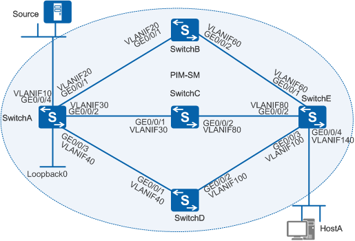
On an IPv6 multicast network as shown in Figure 1, SwitchE connects to HostA and has three equal-cost routes to the multicast source (Source). According to the default RPF check policy, SwitchE will select one of these equal-cost routes to transmit multicast data. When the rate of multicast traffic is high, the network will become congested, lowering the quality of multicast services. To ensure the quality of multicast services, IPv6 multicast load splitting needs to be configured so that multicast data can be transmitted through multiple equal-cost routes.

In this scenario, to avoid loops, ensure that all connected interfaces have STP disabled and connected interfaces are removed from VLAN 1. If STP is enabled and VLANIF interfaces of switches are used to construct a Layer 3 ring network, an interface on the network will be blocked. As a result, Layer 3 services on the network cannot run normally.
Switch |
VLANIF Interface/Loopback Interface |
IPv6 Address |
|---|---|---|
| SwitchA | VLANIF10 | FC00:0:0:2001::2/64 |
| VLANIF20 | FC00:0:0:2002::1/64 | |
| VLANIF30 | FC00:0:0:2003::1/64 | |
| VLANIF40 | FC00:0:0:2004::1/64 | |
| Loopback0 | FC00:0:0:2000::1/64 | |
| SwitchB | VLANIF20 | FC00:0:0:2002::2/64 |
| VLANIF60 | FC00:0:0:2005::1/64 | |
| SwitchC | VLANIF30 | FC00:0:0:2003::2/64 |
| VLANIF80 | FC00:0:0:2006::1/64 | |
| SwitchD | VLANIF40 | FC00:0:0:2004::2/64 |
| VLANIF100 | FC00:0:0:2007::1/64 | |
| SwitchE | VLANIF60 | FC00:0:0:2005::2/64 |
| VLANIF80 | FC00:0:0:2006::2/64 | |
| VLANIF100 | FC00:0:0:2007::2/64 | |
| VLANIF140 | FC00:0:0:3001::2/64 |
Configuration Roadmap
The configuration roadmap is as follows:
Configure IPv6 addresses for interfaces on the switches.
Configure an IPv6 unicast routing protocol, IPv6 Intermediate System-Intermediate System (IS-IS) in this example, to implement interworking among all switches and ensure that route costs are the same.
Enable IPv6 multicast routing on all switches and enable IPv6 Protocol Independent Multicast - Sparse Mode (PIM-SM) on all Layer 3 interfaces. Configure the loopback interface on SwitchA as a candidate bootstrap router (C-BSR) and candidate rendezvous point (C-RP).
On SwitchE, configure stable-preferred IPv6 multicast load splitting to ensure stable transmission of multicast services.
On SwitchE, configure static multicast groups on the interface connected to the network segment of HostA, because HostA needs to receive data of these groups for a long time.
On SwitchE, configure different IPv6 multicast load splitting weights for the interfaces connected to the upstream switches to implement unbalanced load splitting, because HostA needs to receive multicast data of new groups.
Procedure
- Configure IPv6 addresses for interfaces on the switches.
SwitchA is used as an example in the following steps. Configurations
of the other switches are similar.
# Create VLANs and add Layer 2 physical interfaces to the VLANs.
[SwitchA] vlan batch 10 20 30 40
[SwitchA] interface gigabitethernet0/0/4
[SwitchA-GigabitEthernet0/0/4] port link-type hybrid
[SwitchA-GigabitEthernet0/0/4] port hybrid pvid vlan 10
[SwitchA-GigabitEthernet0/0/4] port hybrid untagged vlan 10
[SwitchA-GigabitEthernet0/0/4] quit
[SwitchA] interface gigabitethernet0/0/1
[SwitchA-GigabitEthernet0/0/1] port link-type trunk
[SwitchA-GigabitEthernet0/0/1] port trunk allow-pass vlan 20
[SwitchA-GigabitEthernet0/0/1] quit
[SwitchA] interface gigabitethernet0/0/2
[SwitchA-GigabitEthernet0/0/2] port link-type trunk
[SwitchA-GigabitEthernet0/0/2] port trunk allow-pass vlan 30
[SwitchA-GigabitEthernet0/0/2] quit
[SwitchA] interface gigabitethernet0/0/3
[SwitchA-GigabitEthernet0/0/3] port link-type trunk
[SwitchA-GigabitEthernet0/0/3] port trunk allow-pass vlan 40
[SwitchA-GigabitEthernet0/0/3] quit
# Configure IPv6 addresses and masks for Layer 3 interfaces.
[SwitchA] ipv6
[SwitchA] interface vlanif 10
[SwitchA-Vlanif10] ipv6 enable
[SwitchA-Vlanif10] ipv6 address fc00:0:0:2001::2 64
[SwitchA-Vlanif10] quit
[SwitchA] interface vlanif 20
[SwitchA-Vlanif20] ipv6 enable
[SwitchA-Vlanif20] ipv6 address fc00:0:0:2002::1 64
[SwitchA-Vlanif20] quit
[SwitchA] interface vlanif 30
[SwitchA-Vlanif30] ipv6 enable
[SwitchA-Vlanif30] ipv6 address fc00:0:0:2003::1 64
[SwitchA-Vlanif30] quit
[SwitchA] interface vlanif 40
[SwitchA-Vlanif40] ipv6 enable
[SwitchA-Vlanif40] ipv6 address fc00:0:0:2004::1 64
[SwitchA-Vlanif40] quit
[SwitchA] interface loopback0
[SwitchA-LoopBack0] ipv6 enable
[SwitchA-LoopBack0] ipv6 address fc00:0:0:2000::1 64
[SwitchA-LoopBack0] quit
- Configure Intermediate System to Intermediate System for
IPv6 (IS-IS IPv6) to implement interworking among all the switches
and ensure that route costs are the same (SwitchA as an example).
[SwitchA] isis
[SwitchA-isis-1] ipv6 enable topology standard
[SwitchA-isis-1] network-entity 10.0000.0000.0001.00
[SwitchA-isis-1] quit
[SwitchA] interface vlanif 10
[SwitchA-Vlanif10] isis ipv6 enable
[SwitchA-Vlanif10] quit
[SwitchA] interface vlanif 20
[SwitchA-Vlanif20] isis ipv6 enable
[SwitchA-Vlanif20] quit
[SwitchA] interface vlanif 30
[SwitchA-Vlanif30] isis ipv6 enable
[SwitchA-Vlanif30] quit
[SwitchA] interface vlanif 40
[SwitchA-Vlanif40] isis ipv6 enable
[SwitchA-Vlanif40] quit
[SwitchA] interface loopback0
[SwitchA-LoopBack0] isis ipv6 enable
[SwitchA-LoopBack0] quit
- Enable IPv6 multicast routing on all the switches and enable IPv6 PIM-SM on all Layer 3 interfaces (SwitchA as an example).
[SwitchA] multicast ipv6 routing-enable
[SwitchA] interface vlanif 10
[SwitchA-Vlanif10] pim ipv6 sm
[SwitchA-Vlanif10] quit
[SwitchA] interface vlanif 20
[SwitchA-Vlanif20] pim ipv6 sm
[SwitchA-Vlanif20] quit
[SwitchA] interface vlanif 30
[SwitchA-Vlanif30] pim ipv6 sm
[SwitchA-Vlanif30] quit
[SwitchA] interface vlanif 40
[SwitchA-Vlanif40] pim ipv6 sm
[SwitchA-Vlanif40] quit
[SwitchA] interface loopback 0
[SwitchA-LoopBack0] pim ipv6 sm
[SwitchA-LoopBack0] quit
- Configure a C-BSR and C-RP on SwitchA.
# Configure Loopback0 on SwitchA as a C-BSR and C-RP.
[SwitchA] pim-ipv6
[SwitchA-pim6] c-bsr fc00:0:0:2000::1
[SwitchA-pim6] c-rp fc00:0:0:2000::1
[SwitchA-pim6] quit
- Configure stable-preferred multicast load splitting on
SwitchE.
[SwitchE] multicast ipv6 load-splitting stable-preferred
- Configure static multicast groups on the interface of SwitchE
connected to the network segment of HostA.
# Configure static multicast groups FF13::1 to FF13::3 on VLANIF 140.
[SwitchE] interface vlanif 140
[SwitchE-Vlanif140] mld static-group ff13::1 inc-step-mask 128 number 3
[SwitchE-Vlanif140] quit
- Verify the configuration of stable-preferred multicast
load splitting.
# Source (FC00:0:0:2001::1/64) sends multicast data to multicast groups FF13::1 to FF13::3. HostA can receive multicast data from Source. Brief information about the IPv6 PIM routing table on SwitchE is as follows:
<SwitchE> display pim ipv6 routing-table brief
 VPN-Instance: public net
 Total 3 (*, G) entries; 3 (S, G) entries

  00001.(*, FF13::1)
       Upstream interface:Vlanif60
       Number of downstream:1
  00002.(FC00:0:0:2001::1, FF13::1)
       Upstream interface:Vlanif60
       Number of downstream:1
  00003.(*, FF13::2)
       Upstream interface:Vlanif80
       Number of downstream:1
  00004.(FC00:0:0:2001::1, FF13::2)
       Upstream interface:Vlanif80
       Number of downstream:1
  00005.(*, FF13::3)
       Upstream interface:Vlanif100
       Number of downstream:1
  00006.(FC00:0:0:2001::1, FF13::3)
       Upstream interface:Vlanif100
       Number of downstream:1
(*, G) and (S, G) entries are evenly distributed on the three equal-cost routes. The upstream interfaces of the routes are VLANIF 100, VLANIF 80, and VLANIF 60, respectively.
The load splitting algorithm processes (*, G) and (S, G) entries separately using the same rule.
- Set different multicast load splitting weights for upstream
interfaces of SwitchE to implement uneven multicast load splitting.
# Set the multicast load splitting weight of VLANIF 60 to 3.
[SwitchE] interface vlanif 60
[SwitchE-Vlanif60] multicast ipv6 load-splitting weight 3
[SwitchE-Vlanif60] quit
# Set the multicast load splitting weight of VLANIF 80 to 2
[SwitchE] interface vlanif 80
[SwitchE-Vlanif80] multicast ipv6 load-splitting weight 2
[SwitchE-Vlanif80] quit
- Configure new static multicast groups on the interface
of SwitchE connected to the network segment of HostA.
# Configure static multicast groups FF13::4 to FF13::6 on VLANIF 140.
[SwitchE] interface vlanif 140
[SwitchE-Vlanif140] mld static-group FF13::4 inc-step-mask 128 number 3
[SwitchE-Vlanif140] quit
- Verify the configuration of uneven multicast load splitting.
# Source (FC00:0:0:2001::1/64) sends multicast data to multicast groups FF13::1 to FF13::9. HostA can receive multicast data from Source. Check brief information about the IPv6 PIM routing table on SwitchE.
[SwitchE] display pim ipv6 routing-table brief
 VPN-Instance: public net
 Total 6 (*, G) entries; 6 (S, G) entries

  00001.(*, FF13::1)
       Upstream interface:Vlanif60
       Number of downstream:1
  00002.(FC00:0:0:2001::1, FF13::1)
       Upstream interface:Vlanif60
       Number of downstream:1
  00003.(*, FF13::2)
       Upstream interface:Vlanif80
       Number of downstream:1
  00004.(FC00:0:0:2001::1, FF13::2)
       Upstream interface:Vlanif80
       Number of downstream:1
  00005.(*, FF13::3)
       Upstream interface:Vlanif100
       Number of downstream:1
  00006.(FC00:0:0:2001::1, FF13::3)
       Upstream interface:Vlanif100
       Number of downstream:1
  00007.(*, FF13::4)
       Upstream interface:Vlanif60
       Number of downstream:1
  00008.(FC00:0:0:2001::1, FF13::4)
       Upstream interface:Vlanif60
       Number of downstream:1
  00009.(*, FF13::5)
       Upstream interface:Vlanif60
       Number of downstream:1
  00010.(FC00:0:0:2001::1, FF13::5)
       Upstream interface:Vlanif60
       Number of downstream:1
  00011.(*, FF13::6)
       Upstream interface:Vlanif80
       Number of downstream:1
  00012.(FC00:0:0:2001::1, FF13::6)
       Upstream interface:Vlanif80
       Number of downstream:1
The upstream interfaces of existing (*, G) and (S, G) entries remain unchanged. VLANIF 60 has a larger multicast load splitting weight (3) than VLANIF 80 (2). Therefore, more new (*, G) and (S, G) entries are distributed to the route with VLANIF60 as the upstream interface. The multicast load splitting weight of VLANIF100 is the default value 1, which is smaller than that of VLANIF 60 and VLANIF 80. Therefore, VLANIF 100 does not have new entries.
Configuration Files
SwitchA configuration file
#
sysname SwitchA
#
vlan batch 10 20 30 40
#
ipv6
#
multicast ipv6 routing-enable
#
isis 1
 network-entity 10.0000.0000.0001.00
 #
 ipv6 enable topology standard
 #
#
interface Vlanif10
 ipv6 enable
 ipv6 address FC00:0:0:2001::2/64
 isis ipv6 enable 1
 pim ipv6 sm
#
interface Vlanif20
 ipv6 enable
 ipv6 address FC00:0:0:2002::1/64
 isis ipv6 enable 1
 pim ipv6 sm
#
interface Vlanif30
 ipv6 enable
 ipv6 address FC00:0:0:2003::1/64
 isis ipv6 enable 1
 pim ipv6 sm
#
interface Vlanif40
 ipv6 enable
 ipv6 address FC00:0:0:2004::1/64
 isis ipv6 enable 1
 pim ipv6 sm
#
interface GigabitEthernet0/0/1
 port link-type trunk
 port trunk allow-pass vlan 20
#
interface GigabitEthernet0/0/2
 port link-type trunk
 port trunk allow-pass vlan 30
#
interface GigabitEthernet0/0/3
 port link-type trunk
 port trunk allow-pass vlan 40
#
interface GigabitEthernet0/0/4
 port link-type hybrid
 port hybrid pvid vlan 10
 port hybrid untagged vlan 10
#
interface LoopBack0
 ipv6 enable
 ipv6 address FC00:0:0:2000::1/64
 isis ipv6 enable 1
 pim ipv6 sm
#
pim-ipv6
 c-bsr FC00:0:0:2000::1
 c-rp FC00:0:0:2000::1
#
return
SwitchB configuration file
#
sysname SwitchB
#
vlan batch 20 60
#
ipv6
#
multicast ipv6 routing-enable
#
isis 1
 network-entity 10.0000.0000.0002.00
 #
 ipv6 enable topology standard
 #
#
interface Vlanif20
 ipv6 enable
 ipv6 address FC00:0:0:2002::2/64
 isis ipv6 enable 1
 pim ipv6 sm
#
interface Vlanif60
 ipv6 enable
 ipv6 address FC00:0:0:2005::1/64
 isis ipv6 enable 1
 pim ipv6 sm
#
interface GigabitEthernet0/0/1
 port link-type trunk
 port trunk allow-pass vlan 20
#
interface GigabitEthernet0/0/2
 port link-type trunk
 port trunk allow-pass vlan 60
#
return
SwitchC configuration file
#
sysname SwitchC
#
vlan batch 30 80
#
ipv6
#
multicast ipv6 routing-enable
#
isis 1
 network-entity 10.0000.0000.0003.00
 #
 ipv6 enable topology standard
 #
#
interface Vlanif30
 ipv6 enable
 ipv6 address FC00:0:0:2003::2/64
 isis ipv6 enable 1
 pim ipv6 sm
#
interface Vlanif80
 ipv6 enable
 ipv6 address FC00:0:0:2006::1/64
 isis ipv6 enable 1
 pim ipv6 sm
#
interface GigabitEthernet0/0/1
 port link-type trunk
 port trunk allow-pass vlan 30
#
interface GigabitEthernet0/0/2
 port link-type trunk
 port trunk allow-pass vlan 80
#
return
SwitchD configuration file
#
sysname SwitchD
#
vlan batch 40 100
#
ipv6
#
multicast ipv6 routing-enable
#
isis 1
 network-entity 10.0000.0000.0004.00
 #
 ipv6 enable topology standard
 #
#
interface Vlanif40
 ipv6 enable
 ipv6 address FC00:0:0:2004::2/64
 isis ipv6 enable 1
 pim ipv6 sm
#
interface Vlanif100
 ipv6 enable
 ipv6 address FC00:0:0:2007::1/64
 isis ipv6 enable 1
 pim ipv6 sm
#
interface GigabitEthernet0/0/1
 port link-type trunk
 port trunk allow-pass vlan 40
#
interface GigabitEthernet0/0/2
 port link-type trunk
 port trunk allow-pass vlan 100
#
return
SwitchE configuration file
#
sysname SwitchE
#
vlan batch 60 80 100 140
#
ipv6
#
multicast ipv6 routing-enable
multicast ipv6 load-splitting stable-preferred
#
isis 1
 network-entity 10.0000.0000.0005.00
 #
 ipv6 enable topology standard
 #
#
interface Vlanif60
 ipv6 enable
 ipv6 address FC00:0:0:2005::2/64
 isis ipv6 enable 1
 pim ipv6 sm
 multicast ipv6 load-splitting weight 3
#
interface Vlanif80
 ipv6 enable
 ipv6 address FC00:0:0:2006::2/64
 isis ipv6 enable 1
 pim ipv6 sm
 multicast ipv6 load-splitting weight 2
#
interface Vlanif100
 ipv6 enable
 ipv6 address FC00:0:0:2007::2/64
 isis ipv6 enable 1
 pim ipv6 sm
#
interface Vlanif140
 ipv6 enable
 ipv6 address FC00:0:0:3001::1/64
 isis ipv6 enable 1
 pim ipv6 sm
 mld static-group FF13::1 inc-step-mask 128 number 3
 mld static-group FF13::4 inc-step-mask 128 number 3
#
interface GigabitEthernet0/0/1
 port link-type trunk
 port trunk allow-pass vlan 60
#
interface GigabitEthernet0/0/2
 port link-type trunk
 port trunk allow-pass vlan 80
#
interface GigabitEthernet0/0/3
 port link-type trunk
 port trunk allow-pass vlan 100
#
interface GigabitEthernet0/0/4
 port link-type hybrid
 port hybrid pvid vlan 140
 port hybrid untagged vlan 140
#
return