Example for Configuring SA Message Filtering
Networking Requirements
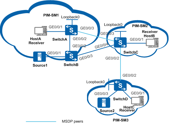
As shown in Figure 1, the network is divided into three PIM-SM domains, and service data is transmitted in multicast mode on the network. Source1 sends multicast data to groups 225.1.1.0/30 and 226.1.1.0/30, and Source2 sends multicast data to the group 227.1.1.0/30. HostA and HostB need to receive only multicast data sent to groups 225.1.1.0/30 and 226.1.1.0/30, and HostC needs to receive only multicast data sent to groups 226.1.1.0/30 and 227.1.1.0/30.

In this scenario, to avoid loops, ensure that all connected interfaces have STP disabled and connected interfaces are removed from VLAN 1. If STP is enabled and VLANIF interfaces of switches are used to construct a Layer 3 ring network, an interface on the network will be blocked. As a result, Layer 3 services on the network cannot run normally.
Switch |
Interfaces and IP Addresses |
|---|---|
SwitchA |
|
SwitchB |
|
SwitchC |
|
SwitchD |
|
Configuration Roadmap
Configure MSDP to enable multicast source information to be shared among domains. Configure SA message filtering to ensure that receivers will receive only required multicast data.
Configure IP addresses for the interfaces on each switch and configure Open Shortest Path First (OSPF) in the PIM-SM domain.
Enable multicast and PIM-SM on each interface. Configure a BootStrap router (BSR) boundary to divide the PIM-SM domain and enable Internet Group Management Protocol (IGMP) on interfaces connected to network segments of receiver hosts.
Configure Loopback0 interfaces on SwitchA, SwitchC, and SwitchD as the candidate bootstrap router (C-BSR) and the candidate rendezvous point (C-RP) of each PIM-SM domain.
Set up MSDP peer relationships between RPs in PIM-SM domains, namely, between SwitchA and SwitchC, and between SwitchC and SwitchD.
Configure SA message filtering rules to prevent SwitchC from forwarding SA messages carrying (Source1, 225.1.1.0/30) to SwitchD, and to prevent SwitchD from creating SA messages carrying Source2 information.
Procedure
- Configure IP addresses for interfaces and configure a unicast
routing protocol on each switch.
# According to Figure 1, configure IP addresses and masks for the interfaces in the PIM-SM domain. Configure OSPF between switches. The configuration details are not mentioned here.
- Enable multicast routing and configure PIM-SM.
# Enable multicast routing on all switches and PIM-SM on all interfaces. Enable IGMP on interfaces connected to network segments of receiver hosts. The following information shows the configuration on SwitchA. The configurations on other switches are similar to the configuration on SwitchA, and are not mentioned here.
[SwitchA] multicast routing-enable
[SwitchA] interface vlanif 100
[SwitchA-Vlanif100] pim sm
[SwitchA-Vlanif100] igmp enable
[SwitchA-Vlanif100] quit
[SwitchA] interface vlanif 101
[SwitchA-Vlanif101] pim sm
[SwitchA-Vlanif101] quit
[SwitchA] interface vlanif 102
[SwitchA-Vlanif102] pim sm
[SwitchA-Vlanif102] quit
[SwitchA] interface loopback 0
[SwitchA-LoopBack0] pim sm
[SwitchA-LoopBack0] quit
- Configure a BSR boundary to divide the PIM-SM domain.
# Configure a BSR boundary on SwitchC. The configurations on SwitchA, SwitchB, and SwitchD are similar to the configuration on SwitchC, and are not mentioned here.
[SwitchC] interface vlanif 101
[SwitchC-Vlanif101] pim bsr-boundary
[SwitchC-Vlanif101] quit
[SwitchC] interface vlanif 103
[SwitchC-Vlanif103] pim bsr-boundary
[SwitchC-Vlanif103] quit
[SwitchC] interface vlanif 104
[SwitchC-Vlanif104] pim bsr-boundary
[SwitchC-Vlanif104] quit
- Configure C-BSRs and C-RPs.
# Configure the C-BSR and C-RP on the Loopback0 interface of SwitchA. The configurations on SwitchC and SwitchD are similar to the configuration on SwitchA, and are not mentioned here.
[SwitchA] pim
[SwitchA-pim] c-bsr loopback0
[SwitchA-pim] c-rp loopback0
[SwitchA-pim] quit
- Configure MSDP peers.
# Configure an MSDP peer on SwitchA.
[SwitchA] msdp
[SwitchA-msdp] peer 192.168.1.2 connect-interface vlanif 101
[SwitchA-msdp] quit
# Configure MSDP peers on SwitchC.
[SwitchC] msdp
[SwitchC-msdp] peer 192.168.1.1 connect-interface vlanif 101
[SwitchC-msdp] peer 10.110.5.2 connect-interface vlanif 104
[SwitchC-msdp] quit
# Configure an MSDP peer on SwitchD.
[SwitchD] msdp
[SwitchD-msdp] peer 10.110.5.1 connect-interface vlanif 104
[SwitchD-msdp] quit
- Configure SA message filtering rules.
# Prohibit SwitchC from forwarding SA messages carrying (Source1, 225.1.1.0/30) to SwitchD.
[SwitchC] acl number 3001
[SwitchC-acl-adv-3001] rule deny ip source 10.110.3.100 0 destination 225.1.1.0 0.0.0.3
[SwitchC-acl-adv-3001] rule permit ip source any destination any
[SwitchC-acl-adv-3001] quit
[SwitchC] msdp
[SwitchC-msdp] peer 10.110.5.2 sa-policy export acl 3001
[SwitchC-msdp] quit
# Prohibit SwitchD from creating SA messages carrying Source2 information.
[SwitchD] acl number 2001
[SwitchD-acl-basic-2001] rule deny source 10.110.6.100 0
[SwitchD-acl-basic-2001] quit
[SwitchD] msdp
[SwitchD-msdp] import-source acl 2001
[SwitchD-msdp] quit
- Verify the configuration.
# Run the display msdp sa-cache command to view information about the (S, G) entries in the SA cache on switches. The following output shows information about the (S, G) entries in the SA cache on SwitchC and SwitchD.
[SwitchC] display msdp sa-cache MSDP Source-Active Cache Information MSDP Total Source-Active Cache - 8 entries MSDP matched 8 entries (10.110.3.100, 225.1.1.0) Origin RP: 10.1.1.1 Pro: ?, AS: ? Uptime: 02:03:30, Expires: 00:05:31 (10.110.3.100, 225.1.1.1) Origin RP: 10.1.1.1 Pro: ?, AS: ? Uptime: 02:03:30, Expires: 00:05:31 (10.110.3.100, 225.1.1.2) Origin RP: 10.1.1.1 Pro: ?, AS: ? Uptime: 02:03:30, Expires: 00:05:31 (10.110.3.100, 225.1.1.3) Origin RP: 10.1.1.1 Pro: ?, AS: ? Uptime: 02:03:30, Expires: 00:05:31 (10.110.3.100, 226.1.1.0) Origin RP: 10.1.1.1 Pro: ?, AS: ? Uptime: 02:03:30, Expires: 00:05:31 (10.110.3.100, 226.1.1.1) Origin RP: 10.1.1.1 Pro: ?, AS: ? Uptime: 02:03:30, Expires: 00:05:31 (10.110.3.100, 226.1.1.2) Origin RP: 10.1.1.1 Pro: ?, AS: ? Uptime: 02:03:30, Expires: 00:05:31 (10.110.3.100, 226.1.1.3) Origin RP: 10.1.1.1 Pro: ?, AS: ? Uptime: 02:03:30, Expires: 00:05:31[SwitchD] display msdp sa-cache MSDP Source-Active Cache Information MSDP Total Source-Active Cache - 4 entries MSDP matched 4 entries (10.110.3.100, 226.1.1.0) Origin RP: 10.1.1.1 Pro: ?, AS: ? Uptime: 00:32:53, Expires: 00:05:07 (10.110.3.100, 226.1.1.1) Origin RP: 10.1.1.1 Pro: ?, AS: ? Uptime: 00:32:53, Expires: 00:05:07 (10.110.3.100, 226.1.1.2) Origin RP: 10.1.1.1 Pro: ?, AS: ? Uptime: 00:32:53, Expires: 00:05:07 (10.110.3.100, 226.1.1.3) Origin RP: 10.1.1.1 Pro: ?, AS: ? Uptime: 00:32:53, Expires: 00:05:07The preceding output shows that only multicast data to multicast groups 225.1.1.0/30 and 226.1.1.0/30 exists in the SA cache on SwitchC, and only multicast data to the multicast groups 226.1.1.0/30 exists in the SA cache on SwitchD.
Configuration Files
SwitchA configuration file
#
sysname SwitchA
#
vlan batch 100 to 102
#
multicast routing-enable
#
interface Vlanif100
 ip address 10.110.1.1 255.255.255.0
 pim sm
 igmp enable
#
interface Vlanif101
 ip address 192.168.1.1 255.255.255.0
 pim bsr-boundary
 pim sm
#
interface Vlanif102
 ip address 10.110.2.1 255.255.255.0
 pim sm
#
interface GigabitEthernet0/0/1
 port link-type hybrid
 port hybrid pvid vlan 100
 port hybrid untagged vlan 100
#
interface GigabitEthernet0/0/2
 port link-type trunk
 port trunk allow-pass vlan 102
#
interface GigabitEthernet0/0/3
 port link-type trunk
 port trunk allow-pass vlan 101
#
interface LoopBack0
 ip address 10.1.1.1 255.255.255.255
 pim sm
#
ospf 1
 area 0.0.0.0
  network 10.1.1.1 0.0.0.0
  network 10.110.1.0 0.0.0.255
  network 10.110.2.0 0.0.0.255
  network 192.168.1.0 0.0.0.255
#
pim
 c-bsr LoopBack0
 c-rp LoopBack0
#
msdp
 peer 192.168.1.2 connect-interface Vlanif101
#
return
SwitchB configuration file
#
sysname SwitchB
#
vlan batch 102 to 103 200
#
multicast routing-enable
#
interface Vlanif102
 ip address 10.110.2.2 255.255.255.0
 pim sm
#
interface Vlanif103
 ip address 192.168.2.1 255.255.255.0
 pim bsr-boundary
 pim sm
#
interface Vlanif200
 ip address 10.110.3.1 255.255.255.0
 pim sm
#
interface GigabitEthernet0/0/1
 port link-type hybrid
 port hybrid pvid vlan 200
 port hybrid untagged vlan 200
#
interface GigabitEthernet0/0/2
 port link-type trunk
 port trunk allow-pass vlan 102
#
interface GigabitEthernet0/0/3
 port link-type trunk
 port trunk allow-pass vlan 103
#
ospf 1
 area 0.0.0.0
  network 10.110.2.0 0.0.0.255
  network 10.110.3.0 0.0.0.255
  network 192.168.2.0 0.0.0.255
#
return
SwitchC configuration file
#
sysname SwitchC
#
vlan batch 101 103 to 104 300
#
multicast routing-enable
#
acl number 3001
 rule 5 deny ip source 10.110.3.100 0 destination 225.1.1.0 0.0.0.3
 rule 10 permit ip
#
interface Vlanif101
 ip address 192.168.1.2 255.255.255.0
 pim bsr-boundary
 pim sm
#
interface Vlanif103
 ip address 192.168.2.2 255.255.255.0
 pim bsr-boundary
 pim sm
#
interface Vlanif104
 ip address 10.110.5.1 255.255.255.0
 pim bsr-boundary
 pim sm
#
interface Vlanif300
 ip address 10.110.4.1 255.255.255.0
 pim sm
 igmp enable
#
interface GigabitEthernet0/0/1
 port link-type hybrid
 port hybrid pvid vlan 300
 port hybrid untagged vlan 300
#
interface GigabitEthernet0/0/2
 port link-type trunk
 port trunk allow-pass vlan 104
#
interface GigabitEthernet0/0/3
 port link-type trunk
 port trunk allow-pass vlan 101
#
interface GigabitEthernet0/0/4
 port link-type trunk
 port trunk allow-pass vlan 103
#
interface LoopBack0
 ip address 10.2.2.2 255.255.255.255
 pim sm
#
ospf 1
 area 0.0.0.0
  network 10.2.2.2 0.0.0.0
  network 10.110.4.0 0.0.0.255
  network 10.110.5.0 0.0.0.255
  network 192.168.1.0 0.0.0.255
  network 192.168.2.0 0.0.0.255
#
pim
 c-bsr LoopBack0
 c-rp LoopBack0
#
msdp
 peer 192.168.1.1 connect-interface Vlanif101
 peer 10.110.5.2 connect-interface Vlanif104
 peer 10.110.5.2 sa-policy export acl 3001
#
return
SwitchD configuration file
#
sysname SwitchD
#
vlan batch 104 400 500
#
multicast routing-enable
#
acl number 2001
 rule 5 deny source 10.110.6.100 0
#
interface Vlanif104
 ip address 10.110.5.2 255.255.255.0
 pim bsr-boundary
 pim sm
#
interface Vlanif400
 ip address 10.110.6.1 255.255.255.0
 pim sm
#
interface Vlanif500
 ip address 10.110.7.1 255.255.255.0
 pim sm
 igmp enable
#
interface GigabitEthernet0/0/1
 port link-type hybrid
 port hybrid pvid vlan 500
 port hybrid untagged vlan 500
#
interface GigabitEthernet0/0/2
 port link-type trunk
 port trunk allow-pass vlan 104
#
interface GigabitEthernet0/0/3
 port link-type hybrid
 port hybrid pvid vlan 400
 port hybrid untagged vlan 400
#
interface LoopBack0
 ip address 10.3.3.3 255.255.255.255
 pim sm
#
ospf 1
 area 0.0.0.0
  network 10.3.3.3 0.0.0.0
  network 10.110.5.0 0.0.0.255
  network 10.110.6.0 0.0.0.255
  network 10.110.7.0 0.0.0.255
#
pim
 c-bsr LoopBack0
 c-rp LoopBack0
#
msdp
 import-source acl 2001
 peer 10.110.5.1 connect-interface Vlanif104
#
return