Example for Configuring MUX VLAN on an Aggregation Device
Networking Requirements
All employees of an enterprise can access the server on the enterprise network. The enterprise allows communication between certain employees while prohibiting communication between others.
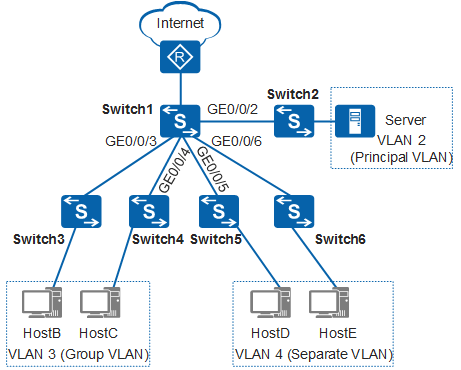
As shown in Figure 1, Switch1 is located at the aggregation layer and used as the gateway of user hosts. Switch2, Switch3, Switch4, Switch5, and Switch6 are access devices. You can configure MUX VLAN on Switch1 to conserve VLAN IDs on the enterprise network. MUX VLAN meets the enterprise's requirements and has fewer requirements on network maintenance.
Configuration Roadmap
The configuration roadmap is as follows:
Configure a principal VLAN and a VLANIF interface. The IP address of the VLANIF interface is used as the gateway IP address of user hosts and server.
Configure a group VLAN.
Configure a separate VLAN.
Add ports to the VLANs and enable the MUX VLAN feature on the ports.
Add ports of access devices to VLANs.
Procedure
- Configure MUX VLAN.
# Create VLAN 2, VLAN 3, VLAN 4, and VLANIF 2 on Switch1. The IP address of VLANIF 2 is used as the gateway IP address for user hosts and server.
<HUAWEI> system-view
[HUAWEI] sysname Switch1
[Switch1] vlan batch 2 3 4
[Switch1] interface vlanif 2
[Switch1-Vlanif2] ip address 192.168.100.100 24
[Switch1-Vlanif2] quit
# Configure a group VLAN and a separate VLAN on Switch1.
[Switch1] vlan 2
[Switch1-vlan2] mux-vlan
[Switch1-vlan2] subordinate group 3
[Switch1-vlan2] subordinate separate 4
[Switch1-vlan2] quit
# Add ports to the VLANs and enable the MUX VLAN feature on the ports.
[Switch1] interface gigabitethernet 0/0/2
[Switch1-GigabitEthernet0/0/2] port link-type trunk
[Switch1-GigabitEthernet0/0/2] port trunk allow-pass vlan 2
[Switch1-GigabitEthernet0/0/2] port mux-vlan enable vlan 2
[Switch1-GigabitEthernet0/0/2] quit
[Switch1] interface gigabitethernet 0/0/3
[Switch1-GigabitEthernet0/0/3] port link-type trunk
[Switch1-GigabitEthernet0/0/3] port trunk allow-pass vlan 3
[Switch1-GigabitEthernet0/0/3] port mux-vlan enable vlan 3
[Switch1-GigabitEthernet0/0/3] quit
[Switch1] interface gigabitethernet 0/0/4
[Switch1-GigabitEthernet0/0/4] port link-type trunk
[Switch1-GigabitEthernet0/0/4] port trunk allow-pass vlan 3
[Switch1-GigabitEthernet0/0/4] port mux-vlan enable vlan 3
[Switch1-GigabitEthernet0/0/4] quit
[Switch1] interface gigabitethernet 0/0/5
[Switch1-GigabitEthernet0/0/5] port link-type trunk
[Switch1-GigabitEthernet0/0/5] port trunk allow-pass vlan 4
[Switch1-GigabitEthernet0/0/5] port mux-vlan enable vlan 4
[Switch1-GigabitEthernet0/0/5] quit
[Switch1] interface gigabitethernet 0/0/6
[Switch1-GigabitEthernet0/0/6] port link-type trunk
[Switch1-GigabitEthernet0/0/6] port trunk allow-pass vlan 4
[Switch1-GigabitEthernet0/0/6] port mux-vlan enable vlan 4
[Switch1-GigabitEthernet0/0/6] quit
- Add ports of access switches to VLANs. The configuration details are not mentioned here.
- Verify the configuration.
The server can communicate with HostB, HostC, HostD, and HostE at Layer 2.
HostB can communicate with HostC at Layer 2.
HostD cannot communicate with HostE at Layer 2.
HostB and HostC cannot communicate with HostD and HostE at Layer 2.
Configuration Files
Switch1 configuration file
#
sysname Switch1
#
vlan batch 2 to 4
#
vlan 2
 mux-vlan
 subordinate separate 4
 subordinate group 3
#
interface Vlanif2
 ip address 192.168.100.100 255.255.255.0
#
interface GigabitEthernet0/0/2
 port link-type trunk
 port trunk allow-pass vlan 2
 port mux-vlan enable vlan 2
#
interface GigabitEthernet0/0/3
 port link-type trunk
 port trunk allow-pass vlan 3
 port mux-vlan enable vlan 3
#
interface GigabitEthernet0/0/4
 port link-type trunk
 port trunk allow-pass vlan 3
 port mux-vlan enable vlan 3
#
interface GigabitEthernet0/0/5
 port link-type trunk
 port trunk allow-pass vlan 4
 port mux-vlan enable vlan 4
#
interface GigabitEthernet0/0/6
 port link-type trunk
 port trunk allow-pass vlan 4
 port mux-vlan enable vlan 4
#
return