Example for Configuring N-to-N Multicast VLAN Replication Based on User VLANs
Networking Requirements
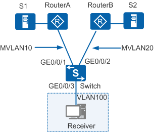
In Figure 1, the Switch is connected to RouterA, RouterB, and the Receiver through GE0/0/1, GE0/0/2, and GE0/0/3, respectively. S1 and S2 are multicast sources provided by different ISPs.
You can configure N-to-N multicast VLAN replication based on user VLANs and distinguish ISPs by different multicast VLANs, so that the user host can receive multicast data sent from S1 to the multicast group 225.1.1.1 and from S2 to the multicast group 225.1.2.1.
Configuration Roadmap
The configuration roadmap is as follows:
- Enable Internet Group Management Protocol (IGMP) snooping in the system view.
- Create a user VLAN and enable IGMP snooping in the user VLAN. Enable the triggering of the multicast flow in the user VLAN.
- Create multicast VLANs and enable IGMP snooping in the multicast VLANs.
- Add the user VLAN to multiple multicast VLANs and configure static multicast flow in the multicast VLANs.
- Add the network-side interfaces and user-side interface to the VLANs as hybrid interfaces.
Procedure
- Enable IGMP snooping in the system view.
<HUAWEI> system-view
[HUAWEI] sysname Switch
[Switch] igmp-snooping enable
- Create user VLAN 100 and enable IGMP snooping in the user VLAN. Enable the triggering of the multicast flow in the user VLAN.
[Switch] vlan 100
[Switch-vlan100] igmp-snooping enable
[Switch-vlan100] multicast flow-trigger enable
[Switch-vlan100] quit
- Create multicast VLANs 10 and 20, and enable the IGMP snooping and IGMP snooping querier functions in the multicast VLANs.
 It is recommended that you configure igmp-snooping querier enable in the multicast VLAN view. If RouterA and RouterB are gateways with IGMP enabled, you do not need to perform this configuration.
[Switch] vlan 10
[Switch-vlan10] igmp-snooping enable
[Switch-vlan10] igmp-snooping querier enable
[Switch-vlan10] multicast-vlan enable
[Switch-vlan10] quit
[Switch] vlan 20
[Switch-vlan20] igmp-snooping enable
[Switch-vlan20] igmp-snooping querier enable
[Switch-vlan20] multicast-vlan enable
[Switch-vlan20] quit
- Add user VLAN 100 to multicast VLANs 10 and 20 and configure static multicast flow in the multicast VLANs.
[Switch] vlan 10
[Switch-vlan10] multicast-vlan user-vlan 100
[Switch-vlan10] multicast static-flow 225.1.1.1
[Switch-vlan10] quit
[Switch] vlan 20
[Switch-vlan20] multicast-vlan user-vlan 100
[Switch-vlan20] multicast static-flow 225.1.2.1
[Switch-vlan20] quit
- Add interfaces to the VLANs as hybrid interfaces.
# Add GE0/0/1 to multicast VLAN 10. Add GE0/0/2 to multicast VLAN 20.
[Switch] interface gigabitethernet 0/0/1
[Switch-GigabitEthernet0/0/1] port link-type hybrid
[Switch-GigabitEthernet0/0/1] port hybrid pvid vlan 10
[Switch-GigabitEthernet0/0/1] port hybrid untagged vlan 10
[Switch-GigabitEthernet0/0/1] quit
[Switch] interface gigabitethernet 0/0/2
[Switch-GigabitEthernet0/0/2] port link-type hybrid
[Switch-GigabitEthernet0/0/2] port hybrid pvid vlan 20
[Switch-GigabitEthernet0/0/2] port hybrid untagged vlan 20
[Switch-GigabitEthernet0/0/2] quit
# Add GE0/0/3 to user VLAN 100.
[Switch] interface gigabitethernet 0/0/3
[Switch-GigabitEthernet0/0/3] port link-type hybrid
[Switch-GigabitEthernet0/0/3] port hybrid pvid vlan 100
[Switch-GigabitEthernet0/0/3] port hybrid untagged vlan 100
[Switch-GigabitEthernet0/0/3] quit
- Verify the configuration.
# Run the display user-vlan vlan command on the Switch. You can see that the user VLAN has been added to multicast VLANs 10 and 20.
[Switch] display user-vlan vlan
 Total user vlan   2
 user-vlan  snooping-state            multicast-vlan  snooping-state
 -----------------------------------------------------------------------------
 100        IGMP Enable/MLD Disable   10              IGMP Enable/MLD Disable
 100        IGMP Enable/MLD Disable   20              IGMP Enable/MLD Disable
# Run the display multicast static-flow command. You can see that the static multicast flow in the multicast VLAN, which indicates that users in the user VLAN can be added to the multicast group.
[Switch] display multicast static-flow
 -------------------------------------------------------------------
 Vlan                                        (Source, Group)
 -------------------------------------------------------------------
  10                                          (*, 225.1.1.1)
  20                                          (*, 225.1.2.1)
 -------------------------------------------------------------------
 Total Table(s) : 2
Configuration Files
Switch configuration file
#
sysname Switch
#
vlan batch 10 20 100
#
igmp-snooping enable
#
vlan 10
 igmp-snooping enable
 igmp-snooping querier enable
 multicast-vlan enable
 multicast static-flow 225.1.1.1
 multicast-vlan user-vlan 100
vlan 20
 igmp-snooping enable
 igmp-snooping querier enable
 multicast-vlan enable
 multicast static-flow 225.1.2.1
 multicast-vlan user-vlan 100
vlan 100
 multicast flow-trigger enable
 igmp-snooping enable
#
interface GigabitEthernet0/0/1
 port link-type hybrid
 port hybrid pvid vlan 10
 port hybrid untagged vlan 10
#
interface GigabitEthernet0/0/2
 port link-type hybrid
 port hybrid pvid vlan 20
 port hybrid untagged vlan 20
#
interface GigabitEthernet0/0/3
 port link-type hybrid
 port hybrid pvid vlan 100
 port hybrid untagged vlan 100
#
return