< Home

Example for Configuring Multicast VPN

Networking Requirements

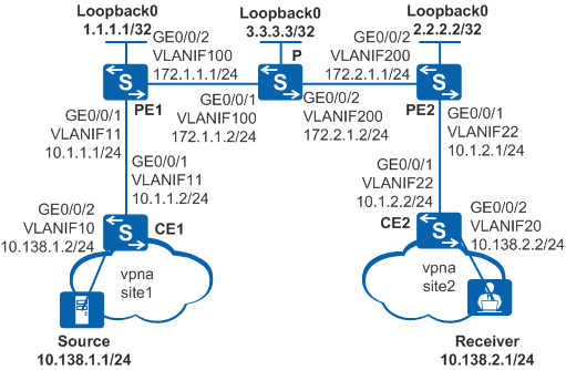
On the network shown in Figure 1, PE1, PE2, and P are backbone devices. CE1 and CE2 are egress devices of two branch networks and belong to VPN instance vpna. MD-based multicast VPN needs to be configured to enable receivers at site2 to receive multicast data traffic of group 225.1.1.1 from site1.

Figure 1 Network diagram for multicast VPN configuration

Configuration Roadmap

The configuration roadmap is as follows:

  1. Configure BGP/MPLS IP VPN to ensure proper operations of VPNs.
  2. Configure a multicast loopback interface, Share-Group address, and multicast tunnel interface (MTI) for the VPN instance on each PE.
  3. Enable multicast routing and PIM globally. Configure multicast functions between the PE and P devices on the public network as well as between PE and CE devices in the VPN instance.

Procedure

  1. Configure BGP/MPLS IP VPN.
    1. Configure Open Shortest Path First (OSPF) on the backbone network to enable communication between PE and P devices.

      # Configure PE1.

      <HUAWEI> system-view
      [HUAWEI] sysname PE1
      [PE1] interface loopback 0
      [PE1-LoopBack0] ip address 1.1.1.1 32
      [PE1-LoopBack0] quit
      [PE1] vlan batch 100
      [PE1] interface gigabitethernet 0/0/2
      [PE1-GigabitEthernet0/0/2] port link-type trunk
      [PE1-GigabitEthernet0/0/2] port trunk allow-pass vlan 100
      [PE1-GigabitEthernet0/0/2] quit
      [PE1] interface vlanif 100
      [PE1-Vlanif100] ip address 172.16.1.1 24
      [PE1-Vlanif100] quit
      [PE1] router id 1.1.1.1
      [PE1] ospf
      [PE1-ospf-1] area 0
      [PE1-ospf-1-area-0.0.0.0] network 172.16.1.0 0.0.0.255
      [PE1-ospf-1-area-0.0.0.0] network 1.1.1.1 0.0.0.0
      [PE1-ospf-1-area-0.0.0.0] quit
      [PE1-ospf-1] quit

      The configurations on P and PE2 are the same as the configuration on PE1

      After the configuration is complete, OSPF neighbor relationships are set up between PE1, P, and PE2. Run the display ospf peer command. The command output should show that the neighbor status is Full. Run the display ip routing-table command. The command output should show that PE1 and PE2 have learned the routes on Loopback 0 from each other.

    2. Configure basic Multiprotocol Label Switching (MPLS) functions. Then enable MPLS Label Distribution Protocol (LDP) to establish LDP label switching paths (LSPs) on the MPLS backbone network.

      # Configure PE1.

      [PE1] mpls lsr-id 1.1.1.1
      [PE1] mpls
      [PE1-mpls] quit
      [PE1] mpls ldp
      [PE1-mpls-ldp] quit
      [PE1] interface vlanif 100
      [PE1-Vlanif100] mpls
      [PE1-Vlanif100] mpls ldp
      [PE1-Vlanif100] quit

      The configurations on P and PE2 are the same as the configuration on PE1.

      After the configuration is complete, LDP sessions can be set up between PE1 and P and between P and PE2. Run the display mpls ldp session command. The command output should show that the LDP session status is Operational.

    3. Set up an MP-IBGP peer relationship between PE1 and PE2.

      # Configure PE1.

      [PE1] bgp 100
      [PE1-bgp] peer 2.2.2.2 as-number 100
      [PE1-bgp] peer 2.2.2.2 connect-interface loopback 0
      [PE1-bgp] ipv4-family vpnv4
      [PE1-bgp-af-vpnv4] peer 2.2.2.2 enable
      [PE1-bgp-af-vpnv4] quit
      [PE1-bgp] quit

      # Configure PE2.

      [PE2] bgp 100
      [PE2-bgp] peer 1.1.1.1 as-number 100
      [PE2-bgp] peer 1.1.1.1 connect-interface loopback 0
      [PE2-bgp] ipv4-family vpnv4
      [PE2-bgp-af-vpnv4] peer 1.1.1.1 enable
      [PE2-bgp-af-vpnv4] quit
      [PE2-bgp] quit

      When the configurations are complete, run the display bgp vpnv4 all peer command on PE1 and PE2. You can see that a BGP peer relationship has been set up the PE devices and is in Established state.

    4. Configure the VPN instance on the PE devices to connect the CE devices to them.

      # Configure PE1.

      [PE1] ip vpn-instance vpna
      [PE1-vpn-instance-vpna] route-distinguisher 100:1
      [PE1-vpn-instance-vpna-af-ipv4] vpn-target 111:1 both
      [PE1-vpn-instance-vpna-af-ipv4] quit
      [PE1-vpn-instance-vpna] quit
      [PE1] vlan batch 11
      [PE1] interface gigabitethernet 0/0/1
      [PE1-GigabitEthernet0/0/1] port link-type trunk
      [PE1-GigabitEthernet0/0/1] port trunk allow-pass vlan 11
      [PE1-GigabitEthernet0/0/1] quit
      [PE1] interface vlanif 11
      [PE1-Vlanif11] ip binding vpn-instance vpna 
      [PE1-Vlanif11] ip address 10.1.1.1 24
      [PE1-Vlanif11] quit

      # Configure PE2.

      [PE2] ip vpn-instance vpna
      [PE2-vpn-instance-vpna] route-distinguisher 100:1
      [PE2-vpn-instance-vpna-af-ipv4] vpn-target 111:1 both
      [PE1-vpn-instance-vpna-af-ipv4] quit
      [PE2-vpn-instance-vpna] quit
      [PE2] vlan batch 22
      [PE2] interface gigabitethernet 0/0/1
      [PE2-GigabitEthernet0/0/1] port link-type trunk
      [PE2-GigabitEthernet0/0/1] port trunk allow-pass vlan 22
      [PE2-GigabitEthernet0/0/1] quit
      [PE2] interface vlanif 22
      [PE2-Vlanif22] ip binding vpn-instance vpna 
      [PE2-Vlanif22] ip address 10.1.2.1 24
      [PE2-Vlanif22] quit

      # Assign IP addresses to the CE interfaces according to Figure 1. The configuration procedure is not detailed here.

      When the configuration is complete, each PE can ping the connected CE using the ping -vpn-instance command.

    5. Configure routes between PE and CE devices and import VPN routes.

      In this example, OSPF is used to advertise routes between PE and CE devices.

      # Configure PE1.

      [PE1] ospf 2 vpn-instance vpna
      [PE1-ospf-2] import-route bgp
      [PE1-ospf-2] area 0
      [PE1-ospf-2-area-0.0.0.0] network 10.1.1.0 0.0.0.255
      [PE1-ospf-2-area-0.0.0.0] quit
      [PE1-ospf-2] quit
      [PE1] bgp 100
      [PE1-bgp] ipv4-family vpn-instance vpna
      [PE1-bgp-vpna] import-route ospf 2
      [PE1-bgp-vpna] quit
      [PE1-bgp] quit

      # Configure CE1.

      [CE1] ospf 1
      [CE1-ospf-1] area 0
      [CE1-ospf-1-area-0.0.0.0] network 10.1.1.0 0.0.0.255
      [CE1-ospf-1-area-0.0.0.0] network 10.138.1.0 0.0.0.255
      [CE1-ospf-1-area-0.0.0.0] quit
      [CE1-ospf-1] quit

      # Configure PE2.

      [PE2] ospf 2 vpn-instance vpna
      [PE2-ospf-2] import-route bgp
      [PE2-ospf-2] area 0
      [PE2-ospf-2-area-0.0.0.0] network 10.1.2.0 0.0.0.255
      [PE2-ospf-2-area-0.0.0.0] quit
      [PE2-ospf-2] quit
      [PE2] bgp 100
      [PE2-bgp] ipv4-family vpn-instance vpna
      [PE2-bgp-vpna] import-route ospf 2
      [PE2-bgp-vpna] quit
      [PE2-bgp] quit

      # Configure CE2.

      [CE2] ospf 1
      [CE2-ospf-1] area 0
      [CE2-ospf-1-area-0.0.0.0] network 10.1.2.0 0.0.0.255
      [CE2-ospf-1-area-0.0.0.0] network 10.138.2.0 0.0.0.255
      [CE2-ospf-1-area-0.0.0.0] quit
      [CE2-ospf-1] quit

      After the configuration is complete, run the display ip routing-table vpn-instance vpna command on PE1 and PE2. You can see that each PE has a route to the remote PE in its VPN routing table. Run the display ip routing-table protocol ospf command on CE1 and CE2. You can see that the CE devices have learned routes from each other.

  2. Configure a multicast loopback interface, Share-Group address, and MTI for the VPN instance on each PE.

    # Configure PE1.

    [PE1] interface eth-trunk 10
    [PE1-Eth-Trunk10] service type multicast-tunnel
    [PE1-Eth-Trunk10] trunkport gigabitethernet 0/0/5
    [PE1-Eth-Trunk10] quit
    [PE1] ip vpn-instance vpna
    [PE1-vpn-instance-vpna] multicast routing-enable 
    [PE1-vpn-instance-vpna] multicast-domain share-group 239.1.1.1 binding mtunnel 0
    [PE1-vpn-instance-vpna] ipv4-family
    [PE1-vpn-instance-vpna-af-ipv4] multicast-domain source-interface loopback 0
    [PE1-vpn-instance-vpna-af-ipv4] quit
    [PE1-vpn-instance-vpna] quit

    # Configure PE2.

    [PE2] interface eth-trunk 10
    [PE2-Eth-Trunk10] service type multicast-tunnel
    [PE2-Eth-Trunk10] trunkport gigabitethernet 0/0/5
    [PE2-Eth-Trunk10] quit
    [PE2] ip vpn-instance vpna
    [PE2-vpn-instance-vpna] multicast routing-enable 
    [PE2-vpn-instance-vpna] multicast-domain share-group 239.1.1.1 binding mtunnel 0
    [PE2-vpn-instance-vpna] ipv4-family
    [PE2-vpn-instance-vpna-af-ipv4] multicast-domain source-interface loopback 0
    [PE2-vpn-instance-vpna-af-ipv4] quit
    [PE2-vpn-instance-vpna] quit

  3. Configure multicast functions on the public network and VPN.
    1. Configure multicast functions on the public network.

      Enable PIM-SM on the public network. Configure Loopback 0 on P as the C-BSR and C-RP.

      # Configure PE1.

      [PE1] multicast routing-enable
      [PE1] interface vlanif 100
      [PE1-Vlanif100] pim sm
      [PE1-Vlanif100] quit
      [PE1] interface loopback 0
      [PE1-LoopBack0] pim sm
      [PE1-LoopBack0] quit

      # Configure PE2.

      [PE2] multicast routing-enable
      [PE2] interface vlanif 200
      [PE2-Vlanif200] pim sm
      [PE2-Vlanif200] quit
      [PE2] interface loopback 0
      [PE2-LoopBack0] pim sm
      [PE2-LoopBack0] quit

      # Configure P.

      [P] multicast routing-enable
      [P] interface vlanif 200
      [P-Vlanif200] pim sm
      [P-Vlanif200] quit
      [P] interface vlanif 100
      [P-Vlanif100] pim sm
      [P-Vlanif100] quit
      [P] interface loopback 0
      [P-LoopBack0] pim sm
      [P-LoopBack0] quit
      [P] pim
      [P-pim] c-bsr Loopback 0 
      [P-pim] c-rp Loopback 0

    2. Configure multicast functions on the VPN.

      Enable PIM-SM on the VPN, and configure VLANIF 11 on CE1 as the C-BSR and C-RP. Configure IGMP for VLANIF 20 of on CE2 connected to receivers.

      # Configure PE1.

      [PE1] interface vlanif 11
      [PE1-Vlanif11] pim sm
      [PE1-Vlanif11] quit

      # Configure PE2.

      [PE2] interface vlanif 22
      [PE2-Vlanif22] pim sm
      [PE2-Vlanif22] quit

      # Configure CE1.

      [CE1] multicast routing-enable
      [CE1] interface vlanif 10
      [CE1-Vlanif10] pim sm
      [CE1-Vlanif10] quit
      [CE1] interface vlanif 11
      [CE1-Vlanif11] pim sm
      [CE1-Vlanif11] quit
      [CE1] pim
      [CE1-pim] c-bsr vlanif 11 
      [CE1-pim] c-rp vlanif 11

      # Configure CE2.

      [CE2] multicast routing-enable
      [CE2] interface vlanif 22
      [CE2-Vlanif22] pim sm
      [CE2-Vlanif22] quit
      [CE2] interface vlanif 20
      [CE2-Vlanif20] pim sm
      [CE2-Vlanif20] igmp enable
      [CE2-Vlanif20] quit
      

  4. Verify the configuration.

    After the preceding configuration is complete, receivers can receive multicast data from the multicast source.

Configuration Files

  • PE1 configuration file

    #
     sysname PE1
    #
     router id 1.1.1.1
    #
    vlan batch 11 100
    # 
     multicast routing-enable
    #
    ip vpn-instance vpna
     ipv4-family
      route-distinguisher 100:1
      vpn-target 111:1 export-extcommunity
      vpn-target 111:1 import-extcommunity
      multicast routing-enable
      multicast-domain source-interface LoopBack0
      multicast-domain share-group 239.1.1.1 binding mtunnel 0
    #
     mpls lsr-id 1.1.1.1
     mpls
    #
     mpls ldp
    #
    interface Vlanif11 
     ip binding vpn-instance vpna
     ip address 10.1.1.1 255.255.255.0
     pim sm
    #
    interface Vlanif100
     ip address 172.16.1.1 255.255.255.0
     pim sm
     mpls
     mpls ldp
    #
    interface Eth-Trunk10
     service type multicast-tunnel
    #
    interface GigabitEthernet0/0/1
     port link-type trunk
     port trunk allow-pass vlan 11
    #
    interface GigabitEthernet0/0/2
     port link-type trunk
     port trunk allow-pass vlan 100
    #
    interface GigabitEthernet0/0/5
     eth-trunk 10
    #
    interface LoopBack0
     ip address 1.1.1.1 255.255.255.255
     pim sm
    #
    interface MTunnel0
     ip binding vpn-instance vpna
    #
    bgp 100
     peer 2.2.2.2 as-number 100
     peer 2.2.2.2 connect-interface LoopBack0
     #
     ipv4-family unicast
      undo synchronization
      peer 2.2.2.2 enable 
     #
     ipv4-family vpnv4
      policy vpn-target
      peer 2.2.2.2 enable
     #
     ipv4-family vpn-instance vpna
      import-route ospf 2
    #
    ospf 1 
     area 0.0.0.0
      network 1.1.1.1 0.0.0.0 
      network 172.16.1.0 0.0.0.255 
    #
    ospf 2 vpn-instance vpna
     import-route bgp 
     area 0.0.0.0 
      network 10.1.1.0 0.0.0.255
    #
    return
  • PE2 configuration file

    #
     sysname PE2
    #
     router id 2.2.2.2
    #
    vlan batch 22 200
    # 
     multicast routing-enable
    #
    ip vpn-instance vpna
     ipv4-family
      route-distinguisher 100:1
      vpn-target 111:1 export-extcommunity
      vpn-target 111:1 import-extcommunity
      multicast routing-enable
      multicast-domain source-interface LoopBack0
      multicast-domain share-group 239.1.1.1 binding mtunnel 0
    #
     mpls lsr-id 2.2.2.2
     mpls
    #
     mpls ldp
    #
    interface Vlanif22
     ip binding vpn-instance vpna
     ip address 10.1.2.1 255.255.255.0
     pim sm
    #
    interface Vlanif200
     ip address 172.17.1.1 255.255.255.0
     pim sm
     mpls
     mpls ldp
    #
    interface Eth-Trunk10
     service type multicast-tunnel
    #
    interface GigabitEthernet0/0/1
     port link-type trunk
     port trunk allow-pass vlan 22
    #
    interface GigabitEthernet0/0/2
     port link-type trunk
     port trunk allow-pass vlan 200
    #
    interface GigabitEthernet0/0/5
     eth-trunk 10
    #
    interface LoopBack0
     ip address 2.2.2.2 255.255.255.255
     pim sm
    #
    interface MTunnel0
     ip binding vpn-instance vpna
    #
    bgp 100
     peer 1.1.1.1 as-number 100
     peer 1.1.1.1 connect-interface LoopBack0
     #
     ipv4-family unicast
      undo synchronization
      peer 1.1.1.1 enable 
     #
     ipv4-family vpnv4
      policy vpn-target
      peer 1.1.1.1 enable
     #
     ipv4-family vpn-instance vpna
       import-route ospf 2
    #
    ospf 1 
     area 0.0.0.0
      network 2.2.2.2 0.0.0.0 
      network 172.17.1.0 0.0.0.255 
    #
    ospf 2 vpn-instance vpna
     import-route bgp
     area 0.0.0.0 
      network 10.1.2.0 0.0.0.255
    #
    return
  • P configuration file

    #
     sysname P
    #
     router id 3.3.3.3
    #
    vlan batch 100 200
    # 
     multicast routing-enable
    #
     mpls lsr-id 3.3.3.3
     mpls
    #
     mpls ldp
    #
    interface Vlanif100 
     ip address 172.16.1.2 255.255.255.0
     pim sm
     mpls
     mpls ldp
    #
    interface Vlanif200
     ip address 172.17.1.2 255.255.255.0
     pim sm
     mpls
     mpls ldp
    #
    interface GigabitEthernet0/0/1
     port link-type trunk
     port trunk allow-pass vlan 100
    #
    interface GigabitEthernet0/0/2
     port link-type trunk
     port trunk allow-pass vlan 200
    #
    interface LoopBack0
     ip address 3.3.3.3 255.255.255.255
     pim sm
    #
    ospf 1 
     area 0.0.0.0
      network 3.3.3.3 0.0.0.0 
      network 172.16.1.0 0.0.0.255 
      network 172.17.1.0 0.0.0.255 
    #
    pim
     c-bsr LoopBack0
     c-rp LoopBack0
    #
    return
  • CE1 configuration file

    #
     sysname CE1
    #
    vlan batch 10 to 11
    # 
     multicast routing-enable
    #
    interface Vlanif10 
     ip address 10.138.1.2 255.255.255.0
     pim sm
    #
    interface Vlanif11
     ip address 10.1.1.2 255.255.255.0
     pim sm
    #
    interface GigabitEthernet0/0/1
     port link-type trunk
     port trunk allow-pass vlan 11
    #
    interface GigabitEthernet0/0/2
     port link-type hybrid
     port hybrid pvid vlan 10
     port hybrid untagged vlan 10
    #
    ospf 1 
     area 0.0.0.0
      network 10.1.1.0 0.0.0.255 
      network 10.138.1.0 0.0.0.255 
    #
    pim
     c-bsr Vlanif11
     c-rp Vlanif11
    #
    return
  • CE2 configuration file

    #
     sysname CE2
    #
    vlan batch 20 22
    # 
     multicast routing-enable
    #
    interface Vlanif20
     ip address 10.138.2.2 255.255.255.0
     pim sm
     igmp enable
    #
    interface Vlanif22
     ip address 10.1.2.2 255.255.255.0
     pim sm
    #
    interface GigabitEthernet0/0/1
     port link-type trunk
     port trunk allow-pass vlan 22
    #
    interface GigabitEthernet0/0/2
     port link-type hybrid
     port hybrid pvid vlan 20
     port hybrid untagged vlan 20
    #
    ospf 1 
     area 0.0.0.0
      network 10.1.2.0 0.0.0.255 
      network 10.138.2.0 0.0.0.255 
    #
    return
Copyright © Huawei Technologies Co., Ltd.
< Previous topic Next topic >