Example for Configuring ECA
Networking Requirements
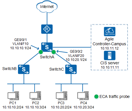
On the network shown in Figure 1, the customer wants to perform ECA on traffic sent from and to SwitchB and SwitchC. The traffic from PC1 is trusted and does not require ECA.
Procedure
- Configure SwitchA.
- Set the resource allocation mode of SwitchA to eca or sac.

On the S5732-H, S6730-H, S6730S-H, S6730-S, and S6730S-S, set the resource allocation mode set to sac. On other switch models, set the resource allocation mode set to eca. The resource allocation takes effect only after the device reboots.
<HUAWEI> system-view
[HUAWEI] assign resource-mode eca
- Enable the IAE.
<HUAWEI> system-view
[HUAWEI] sysname SwitchA
[SwitchA] defence engine enable
- Configure parameters for SwitchA to interoperate with the CIS server.
# Specify the IP address and port number of the CIS server. The CIS server must provide basic big data services.
[SwitchA] flow-probe metadata-collect server ip 10.10.11.11 port 8514
# Specify the source IP address and port number used by SwitchA to connect to the CIS server. The source IP address can be randomly selected from the switch and must be reachable to the CIS server.
[SwitchA] flow-probe metadata-collect source ip 10.10.10.1 port 11111
- Configure an ECA whitelist so that ECA is not performed on the traffic sent from PC1.
# Add a rule in ACL 3000 to allow the traffic with the source address of 10.10.10.2/24 to pass through.
[SwitchA] acl 3000
[SwitchA-acl-adv-3000] rule permit ip source 10.10.10.2 0.0.0.255
[SwitchA-acl-adv-3000] quit
# Add ACL 3000 to the ECA whitelist.
[SwitchA] ec-analytics whitelist acl 3000
- Add VLANIF 10 and VLANIF 20 to the port group named portgroup1, and enable ECA.
[SwitchA] port-group portgroup1
[SwitchA-port-group-portgroup1] group-member vlanif 10 vlanif 20
[SwitchA-port-group-portgroup1] ec-analytics enable
[SwitchA-port-group-portgroup1] quit
Using a port group simplifies the configuration. When ECA needs to be enabled on a few interfaces, you can also complete the configuration on the interfaces one by one.
- Configure a NetStream flexible flow statistics template and apply the template to the physical interfaces corresponding to VLANIF 10 and VLANIF 20.
# Configure a NetStream flexible flow statistics template to aggregate flows based on 5-tuple information and collect statistics about the number of packets, number of bytes, and inbound and outbound interface indexes.
[SwitchA] ip netstream record eca
[SwitchA-record-eca] match ip source-address
[SwitchA-record-eca] match ip destination-address
[SwitchA-record-eca] match ip source-port
[SwitchA-record-eca] match ip destination-port
[SwitchA-record-eca] match ip protocol
[SwitchA-record-eca] collect counter packets
[SwitchA-record-eca] collect counter bytes
[SwitchA-record-eca] collect interface input
[SwitchA-record-eca] collect interface output
[SwitchA-record-eca] collect ip tcp-flag
[SwitchA-record-eca] quit
# Add GE0/0/1 and GE0/0/2 to the port group named portgroup2, enable IPv4 flow statistics collection in the outbound and inbound directions of the interfaces, set the fixed sampling rate to 1:1, and apply the NetStream flexible flow statistics template.
[SwitchA] port-group portgroup2
[SwitchA-port-group-portgroup2] group-member gigabitethernet 0/0/1 gigabitethernet 0/0/2
[SwitchA-port-group-portgroup2] ip netstream inbound
[SwitchA-port-group-portgroup2] ip netstream outbound
[SwitchA-port-group-portgroup2] ip netstream sampler fix-packets 1 inbound
[SwitchA-port-group-portgroup2] ip netstream sampler fix-packets 1 outbound
[SwitchA-port-group-portgroup2] port ip netstream record eca
[SwitchA-port-group-portgroup2] return
# Change the number of digits in the interface index contained in an exported packet carrying IPv4 flow statistics from 16 to 32.
[SwitchA] ip netstream export version 9
[SwitchA] ip netstream export index-switch 32
- Set the resource allocation mode of SwitchA to eca or sac.
- Configure parameters for the CIS server to interoperate with SwitchA.
- Log in to the CIS server using an administrator account.
- Choose and click
 next to Big Data Basic Service.
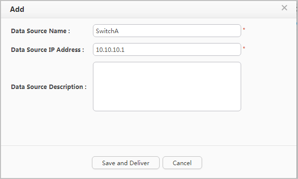
 - On the Third-Party Data Source tab page, click Add, set Data Source Name to SwitchA, set Data Source IP Address to 10.10.10.1, and click Save and Deliver.
- Configure the CIS server to deliver associated policies to the Agile Controller-Campus.
- Configure the Agile Controller-Campus.
- Log in to the Agile Controller-Campus using an administrator account.
- Choose .
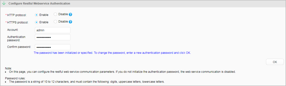
Click Configure Restful Webservice Authentication, enable HTTP protocol and HTTPS protocol, set Account to admin, set both Authentication password and Confirm password to Huawei@2018, and click OK.
- Configure the CIS server.
- Return to the CIS homepage and choose .
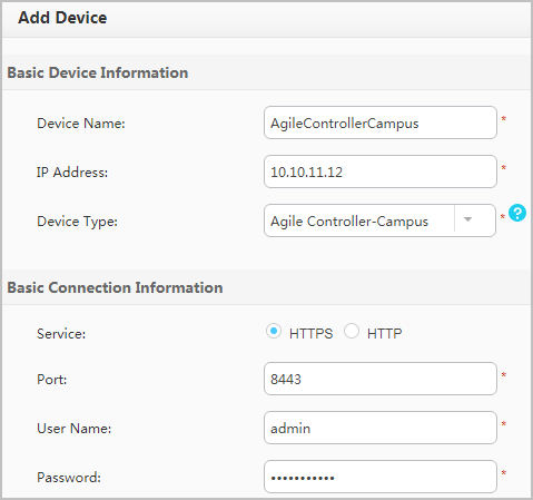
On the Device tab page, click Add, and configure the Agile Controller-Campus information. The user name and password must be the same as those configured on the Agile Controller-Campus. After setting the parameters, click Save.
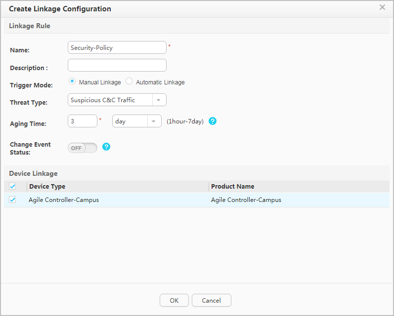
Choose Linkage Rule Conf from the navigation tree. On the Linkage Rule tab page, click Create to create an associated rule. In the Linkage Rule area, set Trigger Mode to Manual Linkage, Threat Type to Suspicious C&C Traffic, and Change Event Status to OFF (if Change Event Status is set to ON, the event status is automatically confirmed). In the Device Linkage area, select Agile Controller-Campus. After setting the parameters, click OK.
- On the Linkage Rule tab page, enable the new associated rule as required. If the rule is enabled, the system automatically changes the status of a successfully associated threat event to a threat. If the rule is not enabled, you need to manually check whether an event is a threat.
- Manually enable the CIS server to deliver associated policies to the Agile Controller-Campus.
- Return to the CIS homepage and choose .
- Set event query parameters and click Search. View events with Event Name being Suspicious C&C Traffic, and view information of IP/Asset under Threat and Threat Source. After confirming an event to be a threat, click
 to manually deliver associated policies to the Agile Controller-Campus to block the traffic.
- Configure the Agile Controller-Campus.
- Verify the configuration.
- View traffic on which ECA is performed.
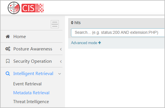
# Log in to the CIS server and choose to view the traffic on which ECA is performed.
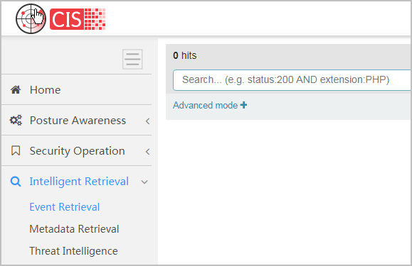
# Choose to view ECA events.
- Check whether the CIS server has delivered the associated rule to the Agile Controller-Campus.
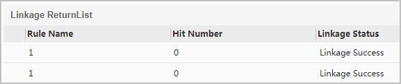
# Choose and click the Results tab to view the blocked traffic. If Linkage Status is displayed Linkage Success, the CIS server has successfully delivered the associated rule to the Agile Controller-Campus. The following figure is for reference only.
- Check whether the Agile Controller-Campus has delivered the associated rule to SwitchA.
# Run the display current-configuration command on SwitchA. If information similar to the following is displayed, the Controller-Campus has blocked attack traffic matching the ACL rule.
[SwitchA] display current-configuration
...
#
acl name Auto_PGM_OPEN_POLICY 3999
 rule 1 deny ip source 192.168.10.3 0 destination 10.10.10.3 0
#
...
#
traffic-secure inbound acl name Auto_PGM_OPEN_POLICY
#
...
- View traffic on which ECA is performed.