Example for Sending Trap Massages to the NMS When the Transmission Delay Threshold Is Exceeded
Networking Requirements
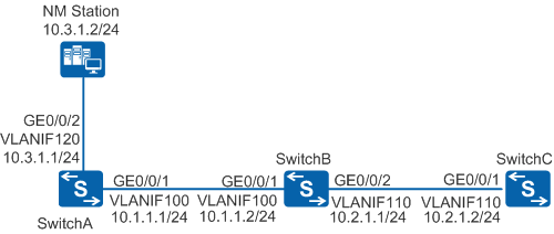
A Jitter test needs to be performed to configure a transmission delay threshold and enable the trap function as shown in Figure 1. After the jitter test is complete, SwitchA sends a trap message to the NMS when the RTT of the test packet exceeds the configured two-way transmission threshold. According to the traps received by the NMS, network administrators can easily locate the fault.
Configuration Roadmap
The configuration roadmap is as follows:
Configure SwitchC as the NQA server and configure the host IP address and port number.
Configure SwitchA as the NQA client, configure a threshold for the NQA alarm, and enable the trap function.
- Create a jitter test instance on SwitchA.
Procedure
- Configure an IP address for each interface and ensure reachable routes between switches, as shown in Figure 1.
# Configure SwitchA.
<HUAWEI> system-view
[HUAWEI] sysname SwitchA
[SwitchA] vlan 100
[SwitchA-vlan100] quit
[SwitchA] interface gigabitethernet 0/0/1
[SwitchA-GigabitEthernet0/0/1] port link-type hybrid
[SwitchA-GigabitEthernet0/0/1] port hybrid pvid vlan 100
[SwitchA-GigabitEthernet0/0/1] port hybrid untagged vlan 100
[SwitchA-GigabitEthernet0/0/1] quit
[SwitchA] interface vlanif 100
[SwitchA-Vlanif100] ip address 10.1.1.1 24
[SwitchA-Vlanif100] quit
[SwitchA] vlan 120
[SwitchA-vlan120] quit
[SwitchA] interface gigabitethernet 0/0/2
[SwitchA-GigabitEthernet0/0/2] port link-type hybrid
[SwitchA-GigabitEthernet0/0/2] port hybrid pvid vlan 120
[SwitchA-GigabitEthernet0/0/2] port hybrid untagged vlan 120
[SwitchA-GigabitEthernet0/0/2] quit
[SwitchA] interface vlanif 120
[SwitchA-Vlanif120] ip address 10.3.1.1 24
[SwitchA-Vlanif120] quit
[SwitchA] ip route-static 10.2.1.0 255.255.255.0 10.1.1.2
# Configure SwitchB.
<HUAWEI> system-view
[HUAWEI] sysname SwitchB
[SwitchB] vlan 100
[SwitchB-vlan100] quit
[SwitchB] vlan 110
[SwitchB-vlan110] quit
[SwitchB] interface gigabitethernet 0/0/1
[SwitchB-GigabitEthernet0/0/1] port link-type hybrid
[SwitchB-GigabitEthernet0/0/1] port hybrid pvid vlan 100
[SwitchB-GigabitEthernet0/0/1] port hybrid untagged vlan 100
[SwitchB-GigabitEthernet0/0/1] quit
[SwitchB] interface vlanif 100
[SwitchB-Vlanif100] ip address 10.1.1.2 24
[SwitchB-Vlanif100] quit
[SwitchB] interface gigabitethernet 0/0/2
[SwitchB-GigabitEthernet0/0/2] port link-type hybrid
[SwitchB-GigabitEthernet0/0/2] port hybrid pvid vlan 110
[SwitchB-GigabitEthernet0/0/2] port hybrid untagged vlan 110
[SwitchB-GigabitEthernet0/0/2] quit
[SwitchB] interface vlanif 110
[SwitchB-Vlanif110] ip address 10.2.1.1 24
[SwitchB-Vlanif110] quit
# Configure SwitchC.
<HUAWEI> system-view
[HUAWEI] sysname SwitchC
[SwitchC] vlan 110
[SwitchC-vlan110] quit
[SwitchC] interface gigabitethernet 0/0/1
[SwitchC-GigabitEthernet0/0/1] port link-type hybrid
[SwitchC-GigabitEthernet0/0/1] port hybrid pvid vlan 110
[SwitchC-GigabitEthernet0/0/1] port hybrid untagged vlan 110
[SwitchC-GigabitEthernet0/0/1] quit
[SwitchC] interface vlanif 110
[SwitchC-Vlanif110] ip address 10.2.1.2 24
[SwitchC-Vlanif110] quit
[SwitchC] ip route-static 10.1.1.0 255.255.255.0 10.2.1.1
- Configure the IP address and port number for monitoring UDP services on SwitchC.
[SwitchC] nqa-server udpecho 10.2.1.2 9000 - Create a jitter test instance on SwitchA.
[SwitchA] nqa test-instance admin jitter
[SwitchA-nqa-admin-jitter] test-type jitter
[SwitchA-nqa-admin-jitter] destination-address ipv4 10.2.1.2
[SwitchA-nqa-admin-jitter] destination-port 9000
- Set a threshold on SwitchA.
# Configure the RTD threshold on SwitchA.
[SwitchA-nqa-admin-jitter] threshold rtd 20 - Enable the trap function on SwitchA.
[SwitchA-nqa-admin-jitter] send-trap rtd[SwitchA-nqa-admin-jitter] quit - Configure traps to be sent to the NMS.
[SwitchA] snmp-agent sys-info version v2c
[SwitchA] snmp-agent community write admin123
[SwitchA] snmp-agent target-host trap address udp-domain 10.3.1.2 params securityname switchA
[SwitchA] snmp-agent trap enable
- Start the test instance.
[SwitchA] nqa test-instance admin jitter[SwitchA-nqa-admin-jitter] start now[SwitchA-nqa-admin-jitter] quit - Check the configuration.
# Check NQA test results on SwitchA.
[SwitchA] display nqa results test-instance admin jitter
 NQA entry(admin, jitter) :testflag is inactive ,testtype is jitter
  1 . Test 1 result   The test is finished
   SendProbe:60                         ResponseProbe:60
   Completion:success                   RTD OverThresholds number:0
   Min/Max/Avg/Sum RTT:1/80/6/331       RTT Square Sum:9341
   NumOfRTT:60                          Drop operation number:0
   Operation sequence errors number:0   RTT Stats errors number:0
   System busy operation number:0       Operation timeout number:0
   Min Positive SD:10                   Min Positive DS:10
   Max Positive SD:40                   Max Positive DS:40
   Positive SD Number:10                Positive DS Number:6
   Positive SD Sum:130                  Positive DS Sum:100
   Positive SD Square Sum:2500          Positive DS Square Sum:2400
   Min Negative SD:10                   Min Negative DS:10
   Max Negative SD:40                   Max Negative DS:30
   Negative SD Number:9                 Negative DS Number:7
   Negative SD Sum:130                  Negative DS Sum:100
   Negative SD Square Sum:2700          Negative DS Square Sum:1800
   Min Delay SD:0                       Min Delay DS:0
   Avg Delay SD:2                       Avg Delay DS:2
   Max Delay SD:40                      Max Delay DS:39
   Packet Loss SD:0                     Packet Loss DS:0
   Packet Loss Unknown:0                Average of Jitter:14
   Average of Jitter SD:13              Average of Jitter DS:15
   Jitter out value:2.5940387           Jitter in value:2.1560009
   NumberOfOWD:60                       OWD SD Sum:145
   OWD DS Sum:126                       TimeStamp unit: ms
   Packet Rewrite Number: 0             Packet Rewrite Ratio: 0%
   Packet Disorder Number: 0            Packet Disorder Ratio: 0%
   Fragment-disorder Number: 0          Fragment-disorder Ratio: 0%
# Check whether traps are generated in the trap buffer. (At the same time, the NMS also receives the traps.)
<SwitchA> display trapbufferTrapping buffer configuration and contents : enabled Allowed max buffer size : 1024 Actual buffer size : 256 Channel number : 3 , Channel name : trapbuffer Dropped messages : 0 Overwritten messages : 3363 Current messages : 256 #Nov 15 2012 16:57:21+06:00 SwitchA NQA/4/RTDTHRESHOLD:OID 1.3.6.1.4.1.2011.5.25.111.6.16 NQA entry RTD over threshold. (OwnerIndex=admin, TestName=jitter)
Configuration Files
SwitchA configuration file
#
sysname SwitchA
#
vlan batch 100 120
#
interface Vlanif100
 ip address 10.1.1.1 255.255.255.0
#
interface Vlanif120
 ip address 10.3.1.1 255.255.255.0
#
interface GigabitEthernet0/0/1
 port link-type hybrid
 port hybrid pvid vlan 100
 port hybrid untagged vlan 100
#
interface GigabitEthernet0/0/2
 port link-type hybrid
 port hybrid pvid vlan 120
 port hybrid untagged vlan 120
#
ip route-static 10.2.1.0 255.255.255.0 10.1.1.2
#
snmp-agent
snmp-agent local-engineid 800007DB0300E009877890
snmp-agent community write cipher %^%#BuDX98e.>CF6_w@~U.TW&(2J*r`dw94l@E)TkK%%Zz>5(|/KEJ>]a+Qe&E-S}R/00tDR:8fy,}2LATeI%^%#
snmp-agent sys-info version v2c v3
snmp-agent target-host trap address udp-domain 10.3.1.2 params securityname cipher %^%#.VYh22r_VPzZ5m2azPQDYh^9:]r~oIFBl[#Aq95*%^%#
snmp-agent trap enable
#
nqa test-instance admin jitter
 test-type jitter
 destination-address ipv4 10.2.1.2
 destination-port 9000
 threshold rtd 20
 send-trap rtd
#
return
SwitchB configuration file
#
sysname SwitchB
#
vlan batch 100 110
#
interface Vlanif100
 ip address 10.1.1.2 255.255.255.0
#
interface Vlanif110
 ip address 10.2.1.1 255.255.255.0
#
interface GigabitEthernet0/0/1
 port link-type hybrid
 port hybrid pvid vlan 100
 port hybrid untagged vlan 100
#
interface GigabitEthernet0/0/2
 port link-type hybrid
 port hybrid pvid vlan 110
 port hybrid untagged vlan 110
#
return
SwitchC configuration file
#
sysname SwitchC
#
vlan batch 110
#
interface Vlanif110
 ip address 10.2.1.2 255.255.255.0
#
interface GigabitEthernet0/0/1
 port link-type hybrid
 port hybrid pvid vlan 110
 port hybrid untagged vlan 110
#
nqa-server udpecho 10.2.1.2 9000
#
ip route-static 10.1.1.0 255.255.255.0 10.2.1.1
#
return