Example for Configuring BFD for OSPFv3
Networking Requirements
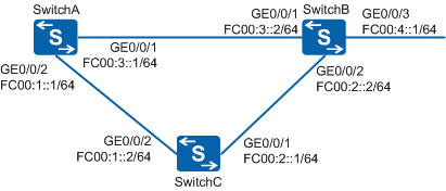
In Figure 1, OSPFv3 is run among SwitchA, SwitchB, and SwitchC. Service traffic is forwarded along the primary link SwitchA→SwitchB. The link SwitchA→SwitchC→SwitchB is used as a backup. Customers require that service traffic be fast switched to the backup link if the primary link fails.

In this scenario, ensure that all connected interfaces have STP disabled. If STP is enabled and VLANIF interfaces of switches are used to construct a Layer 3 ring network, an interface on the network will be blocked. As a result, Layer 3 services on the network cannot run normally.
Configuration Roadmap
The configuration roadmap is as follows:
Configure basic OSPFv3 functions on each switch to make the primary link transmit service traffic properly.
Configure OSPFv3 BFD so that traffic can be fast switched to the backup link if the primary link fails.
Procedure
- Configure IPv6 addresses for interfaces of all switches.
# Configure SwitchA. Ensure that the configurations of SwitchB and SwitchC are the same as that of SwitchA.
<HUAWEI> system-view
[HUAWEI] sysname SwitchA
[SwitchA] ipv6
[SwitchA] interface GigabitEthernet 0/0/1
[SwitchA-GigabitEthernet0/0/1] undo portswitch
[SwitchA-GigabitEthernet0/0/1] ipv6 enable
[SwitchA-GigabitEthernet0/0/1] ipv6 address FC00:3::1 64
[SwitchA-GigabitEthernet0/0/1] quit
[SwitchA] interface GigabitEthernet 0/0/2
[SwitchA-GigabitEthernet0/0/2] undo portswitch
[SwitchA-GigabitEthernet0/0/2] ipv6 enable
[SwitchA-GigabitEthernet0/0/2] ipv6 address FC00:1::1 64
[SwitchA-GigabitEthernet0/0/2] quit
- Configure basic OSPFv3 functions.
# Configure SwitchA.
[SwitchA] ospfv3
[SwitchA-ospfv3-1] router-id 10.1.1.1
[SwitchA-ospfv3-1] quit
[SwitchA] interface GigabitEthernet 0/0/1
[SwitchA-GigabitEthernet0/0/1] ospfv3 1 area 0.0.0.0
[SwitchA-GigabitEthernet0/0/1] quit
[SwitchA] interface GigabitEthernet 0/0/2
[SwitchA-GigabitEthernet0/0/2] ospfv3 1 area 0.0.0.0
[SwitchA-GigabitEthernet0/0/2] quit
# Configure SwitchB.
[SwitchB] ospfv3
[SwitchB-ospfv3-1] router-id 10.2.2.2
[SwitchB-ospfv3-1] quit
[SwitchB] interface GigabitEthernet 0/0/1
[SwitchB-GigabitEthernet0/0/1] ospfv3 1 area 0.0.0.0
[SwitchB-GigabitEthernet0/0/1] quit
[SwitchB] interface GigabitEthernet 0/0/2
[SwitchB-GigabitEthernet0/0/2] ospfv3 1 area 0.0.0.0
[SwitchB-GigabitEthernet0/0/2] quit
[SwitchB] interface GigabitEthernet 0/0/3
[SwitchB-GigabitEthernet0/0/3] ospfv3 1 area 0.0.0.0
[SwitchB-GigabitEthernet0/0/3] quit
# Configure SwitchC.
[SwitchC] ospfv3
[SwitchC-ospfv3-1] router-id 10.3.3.3
[SwitchC-ospfv3-1] quit
[SwitchC] interface GigabitEthernet 0/0/1
[SwitchC-GigabitEthernet0/0/1] ospfv3 1 area 0.0.0.0
[SwitchC-GigabitEthernet0/0/1] quit
[SwitchC] interface GigabitEthernet 0/0/2
[SwitchC-GigabitEthernet0/0/2] ospfv3 1 area 0.0.0.0
[SwitchC-GigabitEthernet0/0/2] quit
# After the preceding configurations are complete, run the display ospfv3 peer command. The following example uses the command output on SwitchA. The command output shows that neighbor relationships are established between SwitchA and SwitchB, and between SwitchB and SwitchC.
[SwitchA] display ospfv3 peer verbose
OSPFv3 Process (1)

 Neighbor 10.3.3.3 is Full, interface address FE80::225:9EFF:FEFB:BFF1
    In the area 0.0.0.0 via interface GE0/0/2
    DR Priority is 1 DR is 10.1.1.1 BDR is 10.3.3.3
    Options is 0x000013 (-|-|-|-|-|-|R|-|-|E|V6)
    Dead timer due in 00:00:31
    Neighbour is up for 00:13:24
    Database Summary Packets List 0
    Link State Request List 0
    Link State Retransmission List 0
    Neighbour Event: 5
    Neighbour If Id : 0xd0
 Neighbor 10.2.2.2 is Full, interface address FE80::201:FF:FE01:1
    In the area 0.0.0.0 via interface GE0/0/1
    DR Priority is 1 DR is 10.1.1.1 BDR is 10.2.2.2
    Options is 0x000013 (-|-|-|-|-|-|R|-|-|E|V6)
    Dead timer due in 00:00:38
    Neighbour is up for 00:13:38
    Database Summary Packets List 0
    Link State Request List 0
    Link State Retransmission List 0
    Neighbour Event: 5
    Neighbour If Id : 0x28
# Check information about the OSPFv3 routing table on SwitchA. The command output shows the routing entries to SwitchB and SwitchC.
[SwitchA] display ospfv3 routing

Codes : E2 - Type 2 External, E1 - Type 1 External, IA - Inter-Area,
        N - NSSA, U - Uninstalled, D - Denied by Import Policy

OSPFv3 Process (1)
     Destination                                               Metric
       Next-hop
     FC00:1::/64                                                   1
       directly connected, GigabitEthernet0/0/2
     FC00:2::/64                                                   2
       via FE80::225:9EFF:FEFB:BFF1, GigabitEthernet0/0/2
       via FE80::201:FF:FE01:1, GigabitEthernet0/0/1
     FC00:3::/64                                                   1
       directly connected, GigabitEthernet0/0/1
     FC00:4::/64                                                   2
       via FE80::201:FF:FE01:1, GigabitEthernet0/0/1
In the OSPFv3 routing table, the next hop of the route to FC00:4::1/64 is GE0/0/1, and traffic is transmitted along the primary link SwitchA→SwitchB.
- Configure OSPFv3 BFD.
# Configure BFD for OSPFv3 on SwitchA.
[SwitchA] bfd
[SwitchA-bfd] quit
[SwitchA] ospfv3
[SwitchA-ospfv3-1] bfd all-interfaces enable
[SwitchA-ospfv3-1] bfd all-interfaces min-transmit-interval 100 min-receive-interval 100 detect-multiplier 4
[SwitchA-ospfv3-1] quit
# Configure BFD for OSPFv3 on SwitchB.
[SwitchB] bfd
[SwitchB-bfd] quit
[SwitchB] ospfv3
[SwitchB-ospfv3-1] bfd all-interfaces enable
[SwitchB-ospfv3-1] bfd all-interfaces min-transmit-interval 100 min-receive-interval 100 detect-multiplier 4
[SwitchB-ospfv3-1] quit
# Configure BFD for OSPFv3 on SwitchC.
[SwitchC] bfd
[SwitchC-bfd] quit
[SwitchC] ospfv3
[SwitchC-ospfv3-1] bfd all-interfaces enable
[SwitchC-ospfv3-1] bfd all-interfaces min-transmit-interval 100 min-receive-interval 100 detect-multiplier 4
[SwitchC-ospfv3-1] quit
After the preceding configurations are complete, run the display ospfv3 bfd session command on SwitchA or SwitchB.
The following example uses the command output on SwitchB as an example. The command output shows that the status of the BFD session is Up.
[SwitchB] display ospfv3 bfd session verbose * - STALE OSPFv3 Process (1) Neighbor-Id: 10.3.3.3 BFD Status: Up Interface: GE0/0/2 IPv6-Local-Address: FE80::201:FF:FE01:1 IPv6-Remote-Address: FE80::225:9EFF:FEFB:BFF1 BFD Module preferred timer values Transmit-Interval(ms): 100 Receive-Interval(ms): 100 Detect-Multiplier: 4 OSPFv3 Module preferred timer values Transmit-Interval(ms): 100 Receive-Interval(ms): 100 Detect-Multiplier: 4 Configured timer values Transmit-Interval(ms): 100 Receive-Interval(ms): 100 Detect-Multiplier: 4 Neighbor-Id: 10.1.1.1 BFD Status: Up Interface: GE0/0/1 IPv6-Local-Address: FE80::201:FF:FE01:1 IPv6-Remote-Address: FE80::200:13FF:FE82:4569 BFD Module preferred timer values Transmit-Interval(ms): 100 Receive-Interval(ms): 100 Detect-Multiplier: 4 OSPFv3 Module preferred timer values Transmit-Interval(ms): 100 Receive-Interval(ms): 100 Detect-Multiplier: 4 Configured timer values Transmit-Interval(ms): 100 Receive-Interval(ms): 100 Detect-Multiplier: 4 - Verify the configuration.
# Run the shutdown command on GE0/0/1 of SwitchB to simulate a primary link fault.
[SwitchB] interface GigabitEthernet 0/0/1
[SwitchB-GigabitEthernet0/0/1] shutdown
# Check the routing table on SwitchA. In the routing table, the backup link SwitchA-SwitchC-SwitchB transmits traffic after the primary link fails, and the next hop of the route to FC00:4::1/64 becomes GE0/0/2.
[SwitchA] display ospfv3 routing

Codes : E2 - Type 2 External, E1 - Type 1 External, IA - Inter-Area,
        N - NSSA, U - Uninstalled, D - Denied by Import Policy

OSPFv3 Process (1)
     Destination                                               Metric
       Next-hop
     FC00:1::/64                                                   1
       directly connected, GigabitEthernet0/0/2
     FC00:2::/64                                                   2
       via FE80::225:9EFF:FEFB:BFF1, GigabitEthernet0/0/2
     FC00:4::/64                                                   3
       via FE80::225:9EFF:FEFB:BFF1, GigabitEthernet0/0/2
Configuration Files
SwitchA configuration file
#
sysname SwitchA
#
ipv6
#
bfd
#
ospfv3 1
 router-id 10.1.1.1
 bfd all-interfaces enable
 bfd all-interfaces min-transmit-interval 100 min-receive-interval 100 detect-multiplier 4
#
interface GigabitEthernet0/0/1
 undo portswitch
 ipv6 enable
 ipv6 address FC00:3::1/64
 ospfv3 1 area 0.0.0.0
#
interface GigabitEthernet0/0/2
 undo portswitch
 ipv6 enable
 ipv6 address FC00:1::1/64
 ospfv3 1 area 0.0.0.0
#
return
SwitchB configuration file
#
sysname SwitchB
#
ipv6
#
bfd
#
ospfv3 1
 router-id 10.2.2.2
 bfd all-interfaces enable
 bfd all-interfaces min-transmit-interval 100 min-receive-interval 100 detect-multiplier 4
#
interface GigabitEthernet0/0/1
 undo portswitch
 ipv6 enable
 ipv6 address FC00:3::2/64
 ospfv3 1 area 0.0.0.0
#
interface GigabitEthernet0/0/2
 undo portswitch
 ipv6 enable
 ipv6 address FC00:2::2/64
 ospfv3 1 area 0.0.0.0
#
interface GigabitEthernet0/0/3
 undo portswitch
 ipv6 enable
 ipv6 address FC00:4::1/64
 ospfv3 1 area 0.0.0.0
#
return
SwitchC configuration file
#
sysname SwitchC
#
ipv6
#
bfd
#
ospfv3 1
 router-id 10.3.3.3
 bfd all-interfaces enable
 bfd all-interfaces min-transmit-interval 100 min-receive-interval 100 detect-multiplier 4
#
interface GigabitEthernet0/0/1
 undo portswitch
 ipv6 enable
 ipv6 address FC00:2::1/64
 ospfv3 1 area 0.0.0.0
#
interface GigabitEthernet0/0/2
 undo portswitch
 ipv6 enable
 ipv6 address FC00:1::2/64
 ospfv3 1 area 0.0.0.0
#
return