Example for Configuring NQA for PBR
Networking Requirements
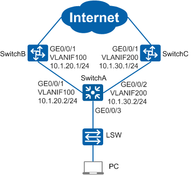
In Figure 1, an enterprise uses SwitchA as an aggregation switch and access switch LSW as a user gateway. There are reachable routes between SwitchA and LSW. SwitchA connects to two core switches, SwitchB and SwitchC, through a high-speed link with the gateway 10.1.20.1/24 and a low-speed link with the gateway 10.1.30.1/24, respectively. A default route has been configured on SwitchA to ensure that traffic is transmitted through the high-speed link by default. The enterprise has the following requirements:
- Use PBR to direct packets with the source IP address 192.168.101.0/24 to the low-speed link. This is to reduce the bandwidth pressure on the high-speed link.
- If the low-speed link becomes faulty, packets with the source IP address 192.168.101.0/24 must be rapidly switched back to the high-speed link to minimize service interruption caused by the link fault.
Configuration Roadmap
- Create VLANs and configure interfaces to connect the enterprise' devices to external network devices.
- Configure an NQA test instance to detect low-speed link quality. This configuration provides a fault detection mechanism for PBR.
- Configure an ACL to match packets with the source address 192.168.101.0/24 that need to be directed to the low-speed link.
- Configure a traffic classifier and bind it to the ACL so that SwitchA can differentiate packets.
- Configure a traffic behavior to redirect packets with the source IP address 192.168.101.0/24 to 10.1.30.1 and configure the NQA test instance for PBR.
- Configure a traffic policy, bind it to the traffic classifier and traffic behavior, and apply it to the inbound direction of GE0/0/3 on SwitchA to associate NQA with PBR.
Procedure
- Specify the VLANs to which interfaces belong.
# Configure SwitchA. The configurations of SwitchB and SwitchC are similar and are not mentioned here.
<HUAWEI> system-view
[HUAWEI] sysname SwitchA
[SwitchA] vlan batch 100 200
[SwitchA] interface gigabitethernet 0/0/1
[SwitchA-GigabitEthernet0/0/1] port link-type trunk
[SwitchA-GigabitEthernet0/0/1] port trunk allow-pass vlan 100
[SwitchA-GigabitEthernet0/0/1] quit
[SwitchA] interface gigabitethernet 0/0/2
[SwitchA-GigabitEthernet0/0/2] port link-type trunk
[SwitchA-GigabitEthernet0/0/2] port trunk allow-pass vlan 200
[SwitchA-GigabitEthernet0/0/2] quit
- Configure an IP address for each VLANIF interface.
# Configure SwitchA. The configurations of SwitchB and SwitchC are similar and are not mentioned here.
[SwitchA] interface vlanif 100
[SwitchA-Vlanif100] ip address 10.1.20.2 24
[SwitchA-Vlanif100] quit
[SwitchA] interface vlanif 200
[SwitchA-Vlanif200] ip address 10.1.30.2 24
[SwitchA-Vlanif200] quit
- Configure an NQA test instance on SwitchA.
[SwitchA] nqa test-instance user test
[SwitchA-nqa-user-test] test-type icmp
[SwitchA-nqa-user-test] destination-address ipv4 10.1.30.1
[SwitchA-nqa-user-test] frequency 11
[SwitchA-nqa-user-test] probe-count 2
[SwitchA-nqa-user-test] interval seconds 5
[SwitchA-nqa-user-test] timeout 4
[SwitchA-nqa-user-test] start now
[SwitchA-nqa-user-test] quit
- Check the NQA test result on SwitchA.
[SwitchA] display nqa results test-instance user test

 NQA entry(user, test) :testflag is active ,testtype is icmp
  1 . Test 288 result   The test is finished
   Send operation times: 2              Receive response times: 2
   Completion:success                RTD OverThresholds number: 0
   Attempts number:1                    Drop operation number:0
   Disconnect operation number:0        Operation timeout number:0
   System busy operation number:0       Connection fail number:0
   Operation sequence errors number:0   RTT Status errors number:0
   Destination ip address:10.1.30.1
   Min/Max/Average Completion Time: 3/4/3
   Sum/Square-Sum  Completion Time: 7/25
   Last Good Probe Time: 2014-09-09 09:55:38.2
   Lost packet ratio: 0 %
If the command output contains Completion:success and Lost packet ratio: 0 %, the NQA test is successful and links are normal.
- Configure an ACL.
# Create an advanced ACL 3001 on SwitchA to permit packets with the source IP address 192.168.101.0/24.
[SwitchA] acl 3001
[SwitchA-acl-adv-3001] rule permit ip source 192.168.101.0 0.0.0.255
[SwitchA-acl-adv-3001] quit
- Configure a traffic classifier.
# Create a traffic classifier c1 on SwitchA, and bind c1 to ACL 3001.
[SwitchA] traffic classifier c1 operator or
[SwitchA-classifier-c1] if-match acl 3001
[SwitchA-classifier-c1] quit
- Configure a traffic behavior.
# Create a traffic behavior b1 on SwitchA to redirect packets to 10.1.30.1, and configure NQA for PBR.
[SwitchA] traffic behavior b1
[SwitchA-behavior-b1] redirect ip-nexthop 10.1.30.1 track-nqa user test
[SwitchA-behavior-b1] quit
- Configure a traffic policy and apply it to an interface.
# Create a traffic policy p1 on SwitchA, and bind it to the traffic classifier and traffic behavior.
[SwitchA] traffic policy p1
[SwitchA-trafficpolicy-p1] classifier c1 behavior b1
[SwitchA-trafficpolicy-p1] quit
# Apply the traffic policy p1 to the inbound direction of GE0/0/3 on SwitchA.
[SwitchA] interface gigabitethernet 0/0/3
[SwitchA-GigabitEthernet0/0/3] traffic-policy p1 inbound
[SwitchA-GigabitEthernet0/0/3] return
- Verify the configuration.
# Check the ACL configuration.
<SwitchA> display acl 3001
Advanced ACL 3001, 1 rule
Acl's step is 5
 rule 5 permit ip source 192.168.101.0 0.0.0.255
# Check the traffic classifier configuration.
<SwitchA> display traffic classifier user-defined
  User Defined Classifier Information:
    Classifier: c1
      Operator: OR
      Rule(s) : if-match acl 3001

Total classifier number is 1
# Check the traffic policy configuration.
<SwitchA> display traffic policy user-defined p1
  User Defined Traffic Policy Information:
  Policy: p1
   Classifier: c1
    Operator: OR
     Behavior: b1
      Redirect: no forced
        Redirect ip-nexthop
        10.1.30.1 track-nqa user test
The preceding command output shows that PBR on SwitchA has been associated with NQA. If a link becomes faulty, PBR on SwitchA becomes ineffective immediately without waiting for the aging of ARP entries. Subsequently, traffic is forwarded according to the IP routing table on SwitchA.
Configuration Files
SwitchA configuration file
#
sysname SwitchA
#
vlan batch 100 200
#
acl number 3001
 rule 5 permit ip source 192.168.101.0 0.0.0.255
#
traffic classifier c1 operator or
 if-match acl 3001
#
traffic behavior b1
 redirect ip-nexthop 10.1.30.1 track-nqa user test
#
traffic policy p1 match-order config
 classifier c1 behavior b1
#
interface Vlanif100
 ip address 10.1.20.2 255.255.255.0
#
interface Vlanif200
 ip address 10.1.30.2 255.255.255.0
#
interface GigabitEthernet0/0/1
 port link-type trunk
 port trunk allow-pass vlan 100
#
interface GigabitEthernet0/0/2
 port link-type trunk
 port trunk allow-pass vlan 200
#
interface GigabitEthernet0/0/3
 traffic-policy p1 inbound
#
nqa test-instance user test
 test-type icmp
 destination-address ipv4 10.1.30.1
 frequency 11
 interval seconds 5
 timeout 4
 probe-count 2
 start now
#
return
SwitchB configuration file
#
sysname SwitchB
#
vlan batch 100
#
interface Vlanif100
 ip address 10.1.20.1 255.255.255.0
#
interface GigabitEthernet0/0/1
 port link-type trunk
 port trunk allow-pass vlan 100
#
return
SwitchC configuration file
#
sysname SwitchC
#
vlan batch 200
#
interface Vlanif200
 ip address 10.1.30.1 255.255.255.0
#
interface GigabitEthernet0/0/1
 port link-type trunk
 port trunk allow-pass vlan 200
#
return