Example for Configuring Policy Association
Networking Requirements
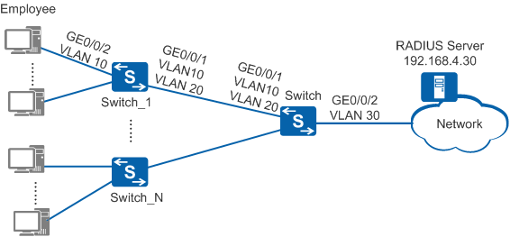
Large campus networks have many authentication access devices, so user access policy deployment is time consuming and the policies are difficult to modify. The customer requires that NAC authentication and user access policies be configured on the authentication gateway and the access policies be implemented on authentication access devices to simplify device deployment at the access layer. As shown in Figure 1, the gateway device Switch functions as the authentication control device and Switch_1-Switch_N are authentication access devices. Users are authenticated on the authentication control device and their access policies are implemented on the authentication access devices. In this example, VLAN 10 is the user VLAN, VLAN 20 is the management VLAN of the CAPWAP tunnel, and 802.1X authentication is used as the access authentication mode.
Configuration Roadmap
The configuration roadmap is as follows:
- Establish CAPWAP tunnels between the authentication control device and authentication access devices.
- Create and configure a RADIUS server template, an AAA scheme, and an authentication domain on the authentication control device so that the RADIUS server can authenticate access users.
- Configure policy association on the authentication control device and all authentication access devices.
- Configure 802.1X authentication on the authentication control device and all authentication access devices, so that the employees' network access rights are controlled and only authenticated users can access the network.

Before configuring this example, ensure that devices can communicate with each other in the network.
This example only provides the configurations on the authentication control device and authentication access devices. The configurations on the RADIUS server are not provided here.
This example only provides the configurations on Switch_1. The configurations on other authentication access devices are the same and not provided here.
Procedure
- Switch the NAC mode to unified mode.# Switch the NAC mode to unified mode on Switch_1.
<HUAWEI> system-view
[HUAWEI] sysname Switch_1
[Switch_1] authentication unified-mode
# Switch the NAC mode to unified mode on Switch.<HUAWEI> system-view [HUAWEI] sysname Switch [Switch] authentication unified-mode
By default, the unified mode is used. After changing the NAC mode from common to unified, you must enter y as prompted to restart the switch immediately to make the configuration take effect.
- Create VLANs and configure the allowed VLANs on interfaces.
# Create VLAN 10 and VLAN 20 on Switch_1.
[Switch_1] vlan batch 10 20# Specify GE0/0/2 connecting Switch_1 to users as an access interface and add the interface to VLAN 10.
[Switch_1] interface gigabitethernet 0/0/2
[Switch_1-GigabitEthernet0/0/2] port link-type access
[Switch_1-GigabitEthernet0/0/2] port default vlan 10
[Switch_1-GigabitEthernet0/0/2] quit
# On Switch_1, specify GE0/0/1 connecting to Switch as a trunk interface and configure the interface to permit packets from VLAN 10 and VLAN 20 to pass through.
[Switch_1] interface gigabitethernet 0/0/1
[Switch_1-GigabitEthernet0/0/1] port link-type trunk
[Switch_1-GigabitEthernet0/0/1] port trunk allow-pass vlan 10 20
[Switch_1-GigabitEthernet0/0/1] quit
# Create VLAN 10, VLAN 20, and VLAN 30 on Switch.
[Switch] vlan batch 10 20 30# On Switch, specify GE0/0/1 connecting to Switch_1 as a trunk interface and configure the interface to permit packets from VLAN 10 and VLAN 20 to pass through.
[Switch] interface gigabitethernet 0/0/1
[Switch-GigabitEthernet0/0/1] port link-type trunk
[Switch-GigabitEthernet0/0/1] port trunk allow-pass vlan 10 20
[Switch-GigabitEthernet0/0/1] quit
# On Switch, specify GE0/0/2 connecting to the RADIUS server as an access interface and add the interface to VLAN 30.
[Switch] interface gigabitethernet 0/0/2
[Switch-GigabitEthernet0/0/2] port link-type access
[Switch-GigabitEthernet0/0/2] port default vlan 30
[Switch-GigabitEthernet0/0/2] quit
[Switch] interface vlanif 30
[Switch-Vlanif30] ip address 192.168.4.1 255.255.255.0
[Switch-Vlanif30] quit
- On the authentication control device, configure the interface address pool VLANIF10 to assign IP addresses to users.
[Switch] dhcp enable
[Switch] interface vlanif 10
[Switch-Vlanif10] ip address 192.168.2.1 255.255.255.0
[Switch-Vlanif10] dhcp select interface
[Switch-Vlanif10] quit
- Establish CAPWAP tunnels between the authentication control device and authentication access devices.
# Create VLANIF 20 on Switch_1, obtain the IP address of VLANIF 20 using DHCP, and specify VLANIF 20 as the access interface of the CAPWAP tunnel.
[Switch_1] interface vlanif 20
[Switch_1-Vlanif20] ip address dhcp-alloc
[Switch_1-Vlanif20] quit
[Switch_1] as access interface vlanif 20
# Create VLANIF 20 on Switch and specify VLANIF 20 as the source interface of the interface address pool and CAPWAP tunnel.
[Switch] interface vlanif 20
[Switch-Vlanif20] ip address 192.168.3.1 255.255.255.0
[Switch-Vlanif20] dhcp select interface
[Switch-Vlanif20] dhcp server option 43 ip-address 192.168.3.1
[Switch-Vlanif20] quit
[Switch] capwap source interface vlanif 20
[Switch] as-auth
[Switch-as-auth] auth-mode none
[Switch-as-auth] quit
- On Switch, create and configure a RADIUS server template, an AAA authentication scheme, and an authentication domain.
# Create and configure a RADIUS server template rd1.
[Switch] radius-server template rd1
[Switch-radius-rd1] radius-server authentication 192.168.4.30 1812
[Switch-radius-rd1] radius-server shared-key cipher Huawei@2012
[Switch-radius-rd1] radius-server retransmit 2
[Switch-radius-rd1] quit
# Create an AAA authentication scheme abc and configure the authentication mode to RADIUS.
[Switch] aaa
[Switch-aaa] authentication-scheme abc
[Switch-aaa-authen-abc] authentication-mode radius
[Switch-aaa-authen-abc] quit
# Create an authentication domain isp1, and bind the AAA scheme abc and RADIUS server template rd1 to the domain isp1.
[Switch-aaa] domain isp1
[Switch-aaa-domain-isp1] authentication-scheme abc
[Switch-aaa-domain-isp1] radius-server rd1
[Switch-aaa-domain-isp1] quit
[Switch-aaa] quit
# Configure the global default domain isp1.
[Switch] domain isp1 During access authentication, enter a user name in the format user@isp1 to perform AAA authentication in the domain isp1. If the user name does not contain a domain name or contains an invalid domain name, the user is authenticated in the default domain.
- Configure policy association on the authentication control device and authentication access devices.
# Specify GE0/0/2 on Switch_1 as the access point.
[Switch_1] interface gigabitethernet 0/0/2
[Switch_1-GigabitEthernet0/0/2] authentication access-point
[Switch_1-GigabitEthernet0/0/2] quit
# Specify GE0/0/1 on Switch as the control point.
[Switch] interface gigabitethernet 0/0/1
[Switch-GigabitEthernet0/0/1] authentication control-point
[Switch-GigabitEthernet0/0/1] quit
# Configure Switch to deliver the ACL authorization information to Switch_1, and bind the AAA service scheme asd to the authentication domain isp1.
[Switch] aaa
[Switch-aaa] service-scheme asd
[Switch-aaa-service-asd] remote-authorize acl
[Switch-aaa-service-asd] quit
[Switch-aaa] domain isp1
[Switch-aaa-domain-isp1] service-scheme asd
[Switch-aaa-domain-isp1] quit
[Switch-aaa] quit
# Configure the ACL and rule for authorization on Switch_1.
[Switch_1] acl 3001
[Switch_1-acl-adv-3001] rule deny ip destination 192.168.5.0 0.0.0.255
[Switch_1-acl-adv-3001] quit
# Configure the ACL and rule for authorization on Switch.
[Switch] acl 3001
[Switch-acl-adv-3001] rule deny ip destination 192.168.5.0 0.0.0.255
[Switch-acl-adv-3001] quit
The number of the ACL configured for authorization on Switch_1 and Switch must be the same as that the RADIUS server delivers to users.
- Configure 802.1X authentication on the authentication control device and authentication access devices.
# Enable 802.1X authentication on GE0/0/2 of Switch_1.
[Switch_1] dot1x-access-profile name d1
[Switch_1-dot1x-access-profile-d1] quit
[Switch_1] authentication-profile name p1
[Switch_1-authen-profile-p1] dot1x-access-profile d1
[Switch_1-authen-profile-p1] quit
[Switch_1] interface gigabitethernet 0/0/2
[Switch_1-GigabitEthernet0/0/2] authentication-profile p1
[Switch_1-GigabitEthernet0/0/2] quit
# Enable 802.1X authentication on GE0/0/1 of Switch and configure an authentication-free rule to allow packets from the management VLAN of the CAPWAP tunnel to pass through.
[Switch] dot1x-access-profile name d1
[Switch-dot1x-access-profile-d1] quit
[Switch] free-rule-template name default_free_rule
[Switch-free-rule-default_free_rule] free-rule 1 source vlan 20
[Switch-free-rule-default_free_rule] quit
[Switch] authentication-profile name p1
[Switch-authen-profile-p1] dot1x-access-profile d1
[Switch-authen-profile-p1] quit
[Switch] interface gigabitethernet 0/0/1
[Switch-GigabitEthernet0/0/1] authentication-profile p1
[Switch-GigabitEthernet0/0/1] quit
- Verify the configuration.
- Run the display dot1x command on the authentication control device and authentication access devices to check the 802.1X authentication configuration. The command output shows that 802.1X authentication has been enabled on GE0/0/2 of Switch_1 and GE0/0/1 of Switch (802.1x protocol is Enabled). Run the display as all command on Switch to check the connection between the authentication control device and authentication access devices.
- A user starts the 802.1X client on a terminal, and enters the user name and password for authentication. If the user name and password are correct, an authentication success message is displayed on the client page. The user then can access the network.
Configuration Files
Switch_1 configuration file
#
sysname Switch_1
#
vlan batch 10 20
#
authentication-profile name p1
 dot1x-access-profile d1
#
as access interface vlanif 20
#
acl number 3001
 rule 5 deny ip destination 192.168.5.0 0.0.0.255
#
interface Vlanif20
 ip address dhcp-alloc
#
interface GigabitEthernet0/0/1
 port link-type trunk
 port trunk allow-pass vlan 10 20
#
interface GigabitEthernet0/0/2
 port link-type access
 port default vlan 10
 authentication-profile p1
 authentication access-point
#
dot1x-access-profile name d1
#
return
Switch configuration file
#
sysname Switch
#
vlan batch 10 20 30
#
authentication-profile name p1
 dot1x-access-profile d1
#
domain isp1
#
dhcp enable
#
radius-server template rd1
 radius-server shared-key cipher %^%#4*SO-2u,Q.\1C~%[eiB77N/^2wME;6t%6U@qAJ9:%^%#
 radius-server authentication 192.168.4.30 1812 weight 80
 radius-server retransmit 2
#
acl number 3001
 rule 5 deny ip destination 192.168.5.0 0.0.0.255
#
free-rule-template name default_free_rule
 free-rule 1 source vlan 20
#
aaa
 authentication-scheme abc
  authentication-mode radius
 service-scheme asd
  remote-authorize acl
 domain isp1
  authentication-scheme abc
  service-scheme asd
  radius-server rd1
#
interface Vlanif10
 ip address 192.168.2.1 255.255.255.0
 dhcp select interface
#
interface Vlanif20
 ip address 192.168.3.1 255.255.255.0
 dhcp select interface
 dhcp server option 43 ip-address 192.168.3.1
#
interface Vlanif30
 ip address 192.168.4.1 255.255.255.0
#
interface GigabitEthernet0/0/1
 port link-type trunk
 port trunk allow-pass vlan 10 20
 authentication-profile p1
 authentication control-point
#
interface GigabitEthernet0/0/2
 port link-type access
 port default vlan 30
#
capwap source interface vlanif20
#
as-auth
 auth-mode none
#
dot1x-access-profile name d1
#
return