Example for Configuring the DHCP Policy VLAN
Networking Requirements
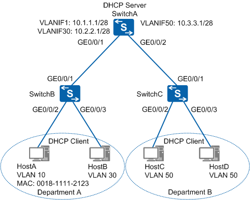
As shown in Figure 1, an enterprise deploys multiple branch networks for departments. SwitchA functions as the DHCP server. Hosts in Department A and Department B connect to SwitchA through SwitchB and SwitchC respectively. Departments are assigned to VLANs based on IP subnets. HostA and HostB in Department A and all hosts in Department B access the network for the first time. HostA with the MAC address 0018-1111-2123 wants to obtain an IP address on the network segment 10.1.1.1/28 and join VLAN 10, and HostB connecting to GE0/0/3 on SwitchB wants to obtain an IP address on the network segment 10.2.2.1/28 and join VLAN 30. All hosts in DepartmentB including HostC and HostD want to obtain IP addresses on the network segment 10.3.3.1/28 and join VLAN 50. To meet the preceding requirements, configure the DHCP policy VLAN on switches.
Configuration Roadmap
The configuration roadmap is as follows:
Configure an interface address pool on SwitchA to assign IP addresses on different network segments to hosts in different departments.
Configure IP subnet-based VLAN assignment on SwitchB and SwitchC interfaces connecting to hosts so that hosts are added to VLANs.
Configure the MAC address-based DHCP policy VLAN on SwitchB so that HostA can obtain an IP address on the network segment 10.1.1.1/28 based on its MAC address.
Configure the interface-based DHCP policy VLAN on SwitchB so that HostB connecting to GE0/0/3 on SwitchB can obtain an IP address on the network segment 10.2.2.1/28.
Configure the generic DHCP policy VLAN on SwitchC so that all hosts in Department B can obtain IP addresses on the network segment 10.3.3.1/28.
Procedure
- Configure an interface address pool on SwitchA.
# Create VLANs on SwitchA and configure IP addresses for VLANIF interfaces.
<HUAWEI> system-view
[HUAWEI] sysname SwitchA
[SwitchA] dhcp enable
[SwitchA] vlan batch 10 30 50
[SwitchA] interface vlanif 10
[SwitchA-Vlanif10] ip address 10.1.1.1 28
[SwitchA-Vlanif10] quit
[SwitchA] interface vlanif 30
[SwitchA-Vlanif30] ip address 10.2.2.1 28
[SwitchA-Vlanif30] quit
[SwitchA] interface vlanif 50
[SwitchA-Vlanif50] ip address 10.3.3.1 28
[SwitchA-Vlanif50] quit
# Enable the VLANIF interface address pools on SwitchA.
[SwitchA] interface vlanif 10
[SwitchA-Vlanif10] dhcp select interface
[SwitchA-Vlanif10] quit
[SwitchA] interface vlanif 30
[SwitchA-Vlanif30] dhcp select interface
[SwitchA-Vlanif30] quit
[SwitchA] interface vlanif 50
[SwitchA-Vlanif50] dhcp select interface
[SwitchA-Vlanif50] quit
# Add interfaces on SwitchA to VLANs.
[SwitchA] interface gigabitethernet 0/0/1
[SwitchA-GigabitEthernet0/0/1] port link-type trunk
[SwitchA-GigabitEthernet0/0/1] port trunk allow-pass vlan 10 30
[SwitchA-GigabitEthernet0/0/1] quit
[SwitchA] interface gigabitethernet 0/0/2
[SwitchA-GigabitEthernet0/0/2] port link-type trunk
[SwitchA-GigabitEthernet0/0/2] port trunk allow-pass vlan 50
[SwitchA-GigabitEthernet0/0/2] quit
- Configure IP subnet-based VLAN assignment on SwitchB and
SwitchC interfaces connecting to hosts.
# Configure IP subnet-based VLAN assignment on GE0/0/2 and GE0/0/3 on SwitchB. Configure the two interfaces as hybrid interfaces and VLAN packets to pass the interfaces in untagged mode.
<HUAWEI> system-view
[HUAWEI] sysname SwitchB
[SwitchB] dhcp enable
[SwitchB] vlan batch 10 30
[SwitchB] interface gigabitethernet 0/0/1
[SwitchB-GigabitEthernet0/0/1] port link-type trunk
[SwitchB-GigabitEthernet0/0/1] port trunk allow-pass vlan 10 30
[SwitchB-GigabitEthernet0/0/1] quit
[SwitchB] interface gigabitethernet 0/0/2
[SwitchB-GigabitEthernet0/0/2] ip-subnet-vlan enable
[SwitchB-GigabitEthernet0/0/2] port hybrid untagged vlan 10
[SwitchB-GigabitEthernet0/0/2] quit
[SwitchB] interface gigabitethernet 0/0/3
[SwitchB-GigabitEthernet0/0/3] ip-subnet-vlan enable
[SwitchB-GigabitEthernet0/0/3] port hybrid untagged vlan 30
[SwitchB-GigabitEthernet0/0/3] quit
# Configure IP subnet-based VLAN assignment on GE0/0/2 and GE0/0/3 on SwitchC. Configure the two interfaces as hybrid interfaces and VLAN packets to pass the interfaces in untagged mode.
<HUAWEI> system-view
[HUAWEI] sysname SwitchC
[SwitchC] dhcp enable
[SwitchC] vlan batch 50
[SwitchC] interface gigabitethernet 0/0/1
[SwitchC-GigabitEthernet0/0/1] port link-type trunk
[SwitchC-GigabitEthernet0/0/1] port trunk allow-pass vlan 50
[SwitchC-GigabitEthernet0/0/1] quit
[SwitchC] interface gigabitethernet 0/0/2
[SwitchC-GigabitEthernet0/0/2] ip-subnet-vlan enable
[SwitchC-GigabitEthernet0/0/2] port hybrid untagged vlan 50
[SwitchC-GigabitEthernet0/0/2] quit
[SwitchC] interface gigabitethernet 0/0/3
[SwitchC-GigabitEthernet0/0/3] ip-subnet-vlan enable
[SwitchC-GigabitEthernet0/0/3] port hybrid untagged vlan 50
[SwitchC-GigabitEthernet0/0/3] quit
- Configure the MAC address-based DHCP policy VLAN on SwitchB
so that HostA can obtain an IP address on the network segment 10.1.1.1/28
based on its MAC address.
[SwitchB] vlan 10
[SwitchB-vlan10] ip-subnet-vlan ip 10.1.1.1 28
[SwitchB-vlan10] dhcp policy-vlan mac-address 0018-1111-2123
[SwitchB-vlan10] quit
- Configure the interface-based DHCP policy VLAN on SwitchB
so that HostB connecting to GE0/0/3 on SwitchB can obtain an IP address
on the network segment 10.2.2.1/28.
[SwitchB] vlan 30
[SwitchB-vlan30] ip-subnet-vlan ip 10.2.2.1 28
[SwitchB-vlan30] dhcp policy-vlan port gigabitethernet 0/0/3
[SwitchB-vlan30] quit
- Configure the generic DHCP policy VLAN on SwitchC so that
all hosts in Department B can obtain IP addresses on the network segment
10.3.3.1/28.
[SwitchC] vlan 50
[SwitchC-vlan50] ip-subnet-vlan ip 10.3.3.1 28
[SwitchC-vlan50] dhcp policy-vlan generic
[SwitchC-vlan50] quit
- Verify the configuration.
# After HostA obtains the IP address 10.1.1.14/28, check the address allocation of VLANIF 10 address pool on SwitchA and ping HostA from SwitchA. The ping succeeds.
[SwitchA] display ip pool interface vlanif10
  Pool-name      : Vlanif10
  Pool-No        : 0
  Lease          : 1 Days 0 Hours 0 Minutes
  Domain-name    : -
  DNS-server0    : -
  NBNS-server0   : -
  Netbios-type   : -
  Position       : Interface       Status           : Unlocked
  Gateway-0      : 10.1.1.1
  Mask           : 255.255.255.240
  VPN instance   : --
 -----------------------------------------------------------------------------
         Start           End     Total  Used  Idle(Expired)  Conflict  Disable
 -----------------------------------------------------------------------------
        10.1.1.1       10.1.1.14    13     1         12(0)         0        0
 -----------------------------------------------------------------------------
[SwitchA] ping 10.1.1.14
  PING 10.1.1.14: 56  data bytes, press CTRL_C to break
    Reply from 10.1.1.14: bytes=56 Sequence=1 ttl=254 time=1 ms
    Reply from 10.1.1.14: bytes=56 Sequence=2 ttl=254 time=1 ms
    Reply from 10.1.1.14: bytes=56 Sequence=3 ttl=254 time=1 ms
    Reply from 10.1.1.14: bytes=56 Sequence=4 ttl=254 time=1 ms
    Reply from 10.1.1.14: bytes=56 Sequence=5 ttl=254 time=1 ms

  --- 10.1.1.14 ping statistics ---
    5 packet(s) transmitted
    5 packet(s) received
    0.00% packet loss
    round-trip min/avg/max = 1/1/1 ms
# After HostB obtains the IP address 10.2.2.14/28, check the address allocation of VLANIF 30 address pool on SwitchA and ping HostB from SwitchA. The ping succeeds.
[SwitchA] display ip pool interface vlanif30
  Pool-name      : Vlanif30
  Pool-No        : 1
  Lease          : 1 Days 0 Hours 0 Minutes
  Domain-name    : -
  DNS-server0    : -
  NBNS-server0   : -
  Netbios-type   : -
  Position       : Interface       Status           : Unlocked
  Gateway-0      : 10.2.2.1
  Mask           : 255.255.255.240
  VPN instance   : --
 -----------------------------------------------------------------------------
         Start           End     Total  Used  Idle(Expired)  Conflict  Disable
 -----------------------------------------------------------------------------
        10.2.2.1       10.2.2.14    13     1         12(0)         0        0
 -----------------------------------------------------------------------------
[SwitchA] ping 10.2.2.14
  PING 10.2.2.14: 56  data bytes, press CTRL_C to break
    Reply from 10.2.2.14: bytes=56 Sequence=1 ttl=254 time=1 ms
    Reply from 10.2.2.14: bytes=56 Sequence=2 ttl=254 time=1 ms
    Reply from 10.2.2.14: bytes=56 Sequence=3 ttl=254 time=1 ms
    Reply from 10.2.2.14: bytes=56 Sequence=4 ttl=254 time=1 ms
    Reply from 10.2.2.14: bytes=56 Sequence=5 ttl=254 time=1 ms

  --- 10.2.2.14 ping statistics ---
    5 packet(s) transmitted
    5 packet(s) received
    0.00% packet loss
    round-trip min/avg/max = 1/1/1 ms
# After HostC and HostD obtain IP addresses 10.3.3.14/28 and 10.3.3.13/28, check the address allocation of VLANIF 50 address pool on SwitchA and ping HostC and HostD from SwitchA respectively. The ping operations succeed.
[SwitchA] display ip pool interface vlanif50
  Pool-name      : Vlanif50
  Pool-No        : 2
  Lease          : 1 Days 0 Hours 0 Minutes
  Domain-name    : -
  DNS-server0    : -
  NBNS-server0   : -
  Netbios-type   : -
  Position       : Interface       Status           : Unlocked
  Gateway-0      : 10.3.3.1
  Mask           : 255.255.255.240
  VPN instance   : --
 -----------------------------------------------------------------------------
         Start           End     Total  Used  Idle(Expired)  Conflict  Disable
 -----------------------------------------------------------------------------
        10.3.3.1       10.3.3.14    13     2         11(0)         0        0
 -----------------------------------------------------------------------------
[SwitchA] ping 10.3.3.14
  PING 10.3.3.14: 56  data bytes, press CTRL_C to break
    Reply from 10.3.3.14: bytes=56 Sequence=1 ttl=254 time=1 ms
    Reply from 10.3.3.14: bytes=56 Sequence=2 ttl=254 time=1 ms
    Reply from 10.3.3.14: bytes=56 Sequence=3 ttl=254 time=1 ms
    Reply from 10.3.3.14: bytes=56 Sequence=4 ttl=254 time=1 ms
    Reply from 10.3.3.14: bytes=56 Sequence=5 ttl=254 time=1 ms

  --- 10.3.3.14 ping statistics ---
    5 packet(s) transmitted
    5 packet(s) received
    0.00% packet loss
    round-trip min/avg/max = 1/1/1 ms
[SwitchA] ping 10.3.3.13
  PING 10.3.3.13: 56  data bytes, press CTRL_C to break
    Reply from 10.3.3.13: bytes=56 Sequence=1 ttl=255 time=11 ms
    Reply from 10.3.3.13: bytes=56 Sequence=2 ttl=254 time=1 ms
    Reply from 10.3.3.13: bytes=56 Sequence=3 ttl=254 time=1 ms
    Reply from 10.3.3.13: bytes=56 Sequence=4 ttl=254 time=1 ms
    Reply from 10.3.3.13: bytes=56 Sequence=5 ttl=254 time=1 ms

  --- 10.3.3.13 ping statistics ---
    5 packet(s) transmitted
    5 packet(s) received
    0.00% packet loss
    round-trip min/avg/max = 1/3/11 ms
Configuration Files
# Configuration file of SwitchA
#
sysname SwitchA
#
vlan batch 10 30 50
#
dhcp enable
#
interface Vlanif10
 ip address 10.1.1.1 255.255.255.240
 dhcp select interface
#
interface Vlanif30
 ip address 10.2.2.1 255.255.255.240
 dhcp select interface
#
interface Vlanif50
 ip address 10.3.3.1 255.255.255.240
 dhcp select interface
#
interface GigabitEthernet0/0/1
 port link-type trunk
 port trunk allow-pass vlan 10 30
#
interface GigabitEthernet0/0/2
 port link-type trunk
 port trunk allow-pass vlan 50
#
return
# Configuration file of SwitchB
#
sysname SwitchB
#
vlan batch 10 30
#
dhcp enable
#
vlan 10
 ip-subnet-vlan 1 ip 10.1.1.1 255.255.255.240
 dhcp policy-vlan mac-address 0018-1111-2123
vlan 30
 ip-subnet-vlan 1 ip 10.2.2.1 255.255.255.240
 dhcp policy-vlan port GigabitEthernet 0/0/3
#
interface GigabitEthernet0/0/1
 port link-type trunk
 port trunk allow-pass vlan 10 30
#
interface GigabitEthernet0/0/2
 port hybrid untagged vlan 10
 ip-subnet-vlan enable
#
interface GigabitEthernet0/0/3
 port hybrid untagged vlan 30
 ip-subnet-vlan enable
#
return
# Configuration file of SwitchC
#
sysname SwitchC
#
vlan batch 50
#
dhcp enable
#
vlan 50
 ip-subnet-vlan 1 ip 10.3.3.1 255.255.255.240
 dhcp policy-vlan generic
#
interface GigabitEthernet0/0/1
 port link-type trunk
 port trunk allow-pass vlan 50
#
interface GigabitEthernet0/0/2
 port hybrid untagged vlan 50
 ip-subnet-vlan enable
#
interface GigabitEthernet0/0/3
 port hybrid untagged vlan 50
 ip-subnet-vlan enable
#
return