PTP Fundamentals
Concepts of Clock Synchronization
Telecommunications services on modern communications networks require that the frequency offset or time difference between devices be within an acceptable range. This requirement must be met using network clock synchronization.
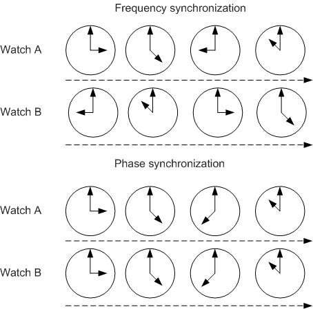
Clock synchronization includes frequency synchronization and phase synchronization.
Frequency synchronization
Frequency synchronization, also called clock synchronization, indicates that signals have the same frequency and a fixed phase difference. That is, signals are sent or received at an average rate. All devices on a communications network operate at the same rate.
Phase synchronization
Phase synchronization, also called time synchronization, indicates that both frequencies and phases of signals are consistent. That is, the phase offset between signals is always 0.
In the following sections, time synchronization indicates phase synchronization, and clock synchronization indicates both phase synchronization and frequency synchronization.
Clock Synchronization Implementation
A network that implements clock synchronization between network devices is called a clock synchronization network. Such a network uses a two-level architecture, as shown in Figure 2. Level-1 nodes are level-1 clock synchronization devices, level-2 nodes are level-2 clock synchronization devices, and nodes below level-2 nodes are clients that require clock synchronization.
A client clock synchronization link connects a node and a client. Any transmission link can be used as a client clock synchronization link because multiple synchronization methods, including Ethernet clock synchronization and Network Time Protocol (NTP), are required between nodes and clients. A node clock synchronization link connects two nodes. Any transmission link except a link that runs NTP can be used as a node clock synchronization link.
PTP organizes all clocks into a master-slave synchronization hierarchy, with the grandmaster clock at the top of the hierarchy. PTP messages are used to implement clock synchronization. To synchronize its local clock with the master clock in the hierarchy, a slave clock uses the timestamp carried in PTP messages to calculate its offset and delay compared with the master clock.

Basic Concepts
PTP domain
A PTP domain is a logical area that runs PTP. More than one PTP domains may exist on a network. Each PTP domain is an independent PTP clock synchronization system and has only one clock source. All devices in a PTP domain synchronize their clocks with the clock source.
1588v2 clock nodes
Clock nodes are nodes in a PTP domain. PTP defines the following types of clock nodes:- Ordinary clock (OC) device: provides only one physical port to participate in time synchronization in a PTP domain. An OC device uses this port to synchronize time with an upstream device or to send time to a downstream device.
- Boundary clock (BC) device: provides two or more physical ports to participate in time synchronization in a PTP domain. One port synchronizes time with an upstream device, and the others send the time to downstream devices. A clock node is also a BC device if it functions as the clock source and sends time to downstream devices through multiple PTP ports.
- Transparent clock (TC) device: forwards PTP messages between its PTP ports and measures the link delay of the messages. Different from an OC device and a BC device, a TC device does not synchronize time with other devices through ports.
- 1588v2 clock types
- OC: ordinary clock
- BC: boundary clock
- End to end transparent clock (E2ETC) for the delay mechanism: is a TC using a delay measurement mechanism in delay mode. A device that functions as an E2ETC does not need to have the delay measurement mechanism mode configured.
- Peer to peer transparent clock (P2PTC) for the Pdelay mechanism: is a TC using a delay measurement mechanism in Pdelay mode. A device that functions as a P2PTC does not need to have the delay measurement mechanism mode configured.
- End to end transparent clock (E2ETC) for the delay mechanism: is an ordinary TC in terms of time synchronization and a special TC that synchronizes the frequency with upstream devices based on PTP messages. For an E2ETCOC, the ports that function as a TC work in the delay measurement mechanism.
- Peer to peer transparent clock and ordinary clock (P2PTCOC): is similar to an E2ETCOC. For a P2PTCOC, the ports that function as a TC work in the Pdelay measurement mechanism.
- Transparent clock and boundary clock (TCandBC): For a TCandBC, some PTP ports function as a BC that synchronizes the clock with other devices, and other PTP ports function as a TC that transmits PTP messages and does not perform delay calculation.
G.8275.1 clock nodes
The clock nodes supported by G.8275.1 are as follows:- Telecom grandmaster (T-GM): is a master-only clock that can have one or more PTP ports. It does not trace other PTP clocks.
- Telecom boundary clock (T-BC): can be a master clock and trace other PTP clocks.
- Telecom time slave clock (T-TSC): is a slave-only clock.
G.8275.1 clock type: T-BC
PTP port
A PTP port is a port running PTP. PTP ports are classified into the following types based on roles:- Master port: is located on a BC, T-BC, or OC device and sends synchronization clock signals to a downstream port.
- Slave port: is located on a BC, T-BC, or OC device and receives synchronization clock signals from an upstream port.
- Passive port: is an idle port on a T-BC or BC device and does not send or receive synchronization clock signals.
Master-slave hierarchy
Nodes in a PTP domain are organized into a master-slave hierarchy. Master nodes send synchronization clock signals, whereas slave nodes receive synchronization clock signals. A device may receive synchronization clock signals from an upstream node and then send the synchronization clock signals to a downstream device.
If two clock nodes synchronize time with each other:
- The node that sends synchronization clock signals is the master node, and the node that receives synchronization clock signals is the slave node.
- The clock on the master node is the master clock, and the clock on the slave node is the slave clock.
- The port that sends synchronization clock signals is the master port, and the port that receives synchronization clock signals is the slave port.
Grandmaster clock
All clock nodes in a PTP domain are organized into a master-slave hierarchy. The grandmaster clock (GMC) is at the top of the hierarchy and serves as the reference clock. Clock nodes exchange PTP messages to synchronize the time of the GMC to the entire PTP domain. Therefore, the GMC is also called the clock source. The GMC can be statically configured or dynamically elected through the best master clock (BMC) algorithm.
PTP message
Nodes exchange PTP messages to establish the master-slave hierarchy and implement time and frequency synchronization. PTP messages are classified into event messages and general messages depending on timestamps:- Event message: is tagged with a timestamp when reaching or leaving a port. PTP devices calculate the link delay based on the timestamps carried in event messages. Event messages include Sync, Delay_Req, Pdelay_Req, and Pdelay_Resp messages.
- General message: is used to establish master-slave hierarchy, and to request and send time information. General messages are not tagged with timestamps. General messages include Announce, Follow_Up, Delay_Resp, Pdelay_Resp_Follow_Up, Management, and Signaling messages. Currently, devices do not support Management and Signaling messages.
Message
1588v2
G.8275.1
Function
Sync
Supported
Supported
A Sync message is sent from the master to the slave and carries the t1 timestamp sent by the master.
A Sync message can be sent in either one-step or two-step mode.- one-step: In this mode, a Sync message contains the transmit timestamp.
- two-step: In this mode, a Sync message records the time when the message is sent, instead of containing the transmit timestamp. Such a transmit timestamp is carried in a Follow-Up message.
Delay_Req
Supported
Supported
A Delay_Req message is sent from the slave to the master during delay time synchronization and carries the t3 timestamp sent by the slave.
Pdelay_Req
Supported
Not supported
A Pdelay_Req message is sent from the slave to the master during peer delay time synchronization and carries the t3 timestamp sent by the slave.
Pdelay_Resp
Supported
Not supported
A Pdelay_Resp message is sent by the master to the slave during peer delay time synchronization and carries the t4 timestamp and interface ID sent by the master.
Announce
Supported
Supported
An Announce message is used to exchange time source information between clock nodes to determine the master-slave hierarchy.
Follow_Up
Supported
Supported
A Follow_Up message is sent from the master to the slave following a Sync message in two-way mode during delay time synchronization. A Follow_Up message carries the t1 timestamp sent by the master.
Delay_Resp
Supported
Supported
A Delay_Resp message is sent by the master to the slave during delay time synchronization and carries the t4 timestamp and interface ID sent by the master.
Pdelay_Resp_Follow_Up
Supported
Not supported
A Pdelay_Resp_Follow_Up message is sent from the master to the slave following a Sync message in two-way mode during peer delay time synchronization. A Pdelay_Resp_Follow_Up message carries the t1 timestamp sent by the master.
Management
Supported
Not supported
Currently, a switch does not support Management messages.
Signaling
Supported
Not supported
Packet Encapsulation Modes
1588v2 message encapsulation modes
MAC encapsulation
This mode applies to 1588v2 messages that are transmitted over a Layer 2 link. In MAC encapsulation, the VLAN ID and 802.1p priority can be carried in 1588v2 messages, and the Ethernet type 0x88F7 is used.
Figure 3 Untagged MAC-encapsulated messages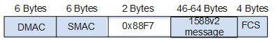 Figure 4 Tagged MAC-encapsulated messages
UDP encapsulation
This mode applies to 1588v2 messages that are transmitted over a Layer 3 link. In UDP encapsulation, the VLAN ID, 802.1p priority, and DSCP priority can be carried in 1588v2 messages, and the destination UDP port number is 319 (for non-Announce messages) or 320 (for Announce messages).
Figure 5 Untagged UDP-encapsulated messages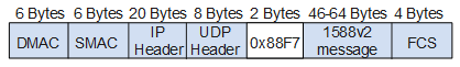 Figure 6 Tagged UDP-encapsulated messages
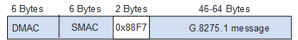
G.8275.1 packet encapsulation modes
G.8275.1 defines the packet encapsulation mode as Layer 2 multicast (without tags). The corresponding Ethernet Type is 0x88F7. There are two types of multicast destination MAC addresses: non-forwardable multicast MAC address (0180-C200-000E) and forwardable multicast MAC address (011B-1900-0000).
Clock Synchronization Process
The clock synchronization process consists of three phases:
Master-slave hierarchy establishment
PTP selects the GMC and determines the master and slave ports.
Frequency synchronization
PTP synchronizes the frequency of the slave node with that of the master node.
Time synchronization
PTP synchronizes the time of the slave node with that of the master node.
Comparisons between synchronous Ethernet and other clock synchronization protocols
Clock Protocol |
Whether Frequency Synchronization Is Supported |
Whether Time Synchronization Is Supported |
Time Synchronization Accuracy |
Signal Transmission Mode |
|---|---|---|---|---|
NTP |
No |
Yes |
Millisecond accuracy |
Time signals are transmitted using NTP packets. |
Synchronous Ethernet |
Yes |
No |
- |
Clock signals are transmitted using serial data streams at the physical layer, without affecting upper-layer services and CPU performance. |
PTP |
Yes |
Yes |
Sub-microsecond accuracy |
Clock and time signals are transmitted using PTP packets, and higher time accuracy is achieved with the assistance of hardware. |