Example for Configuring a Dynamic Single-hop PW
Networking Requirements
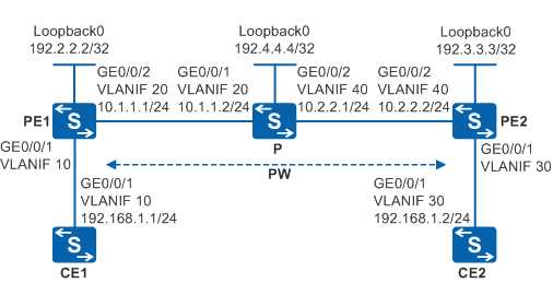
As shown in Figure 1, the carrier MPLS network provides L2VPN services for users and PE1 and PE2 connect to many users with variable quantities. A VPN solution is required to provide secure VPN services for users, save network resources, and allow easy configuration for new access users.

By default, LNP is enabled globally on the device. If a VLANIF interface is used as an AC-side interface for L2VPN, the configuration conflicts with LNP. In this case, run the lnp disable command in the system view to disable LNP.
The lnp disable command has no impact on services before the device restarts. After the device restarts, the device can only forward packets from the VLANs specified by the port default vlan command at Layer 2. The port default vlan 1 command is configured by default, so only packets of VLAN 1 can be forwarded at Layer 2.
Configuration Roadmap
Because users on the two PEs often change, there is low efficiency in manually synchronizing user information and error may occur. You can establish a remote LDP connection between the two PEs so that PEs synchronize user information using LDP. That is, a dynamic PW is used. Compared with Martini, PWE3 reduces the signaling cost, and defines the multi-hop negotiation mode. This makes networking flexible. To save network resources as much as possible, PWE3 is recommended.
The configuration roadmap is as follows:
Configure an IGP protocol on the backbone network so that backbone network devices can communicate.
Configure basic MPLS functions and establish LSP tunnels on the backbone network. Then establish the remote MPLS LDP peer relationship between PEs at both ends of the PW.
Create MPLS L2VC connections on PEs.
Procedure
- Configure VLANs that the interfaces of CEs, PEs, and P belong to and set the IP addresses of the corresponding VLANIF interfaces according to Figure 1.
# Configure CE1. The configuration on PE1, PE2, P, and CE2 is similar to the CE1, and is not mentioned here.
<HUAWEI> system-view
[HUAWEI] sysname CE1
[CE1] vlan batch 10
[CE1] interface vlanif 10
[CE1-Vlanif10] ip address 192.168.1.1 255.255.255.0
[CE1-Vlanif10] quit
[CE1] interface gigabitethernet 0/0/1
[CE1-GigabitEthernet0/0/1] port link-type trunk
[CE1-GigabitEthernet0/0/1] port trunk allow-pass vlan 10
[CE1-GigabitEthernet0/0/1] quit
- Configure an IGP protocol on the MPLS backbone network.
Configure an IGP protocol on the MPLS backbone network. This example uses OSPF.
The display on PE1 is used as an example.
# Configure PE1. The configuration on PE2 and P is similar to the PE1, and is not mentioned here.
[PE1]  interface loopback 0
[PE1-LoopBack0] ip address 192.2.2.2 255.255.255.255
[PE1-LoopBack0] quit
[PE1] ospf 1
[PE1-ospf-1] area 0
[PE1-ospf-1-area-0.0.0.0] network 192.2.2.2 0.0.0.0
[PE1-ospf-1-area-0.0.0.0] network 10.1.1.0 0.0.0.255
[PE1-ospf-1-area-0.0.0.0] quit
[PE1-ospf-1] quit
After the configuration is complete, run the display ip routing-table command. You can see that PE1 and PE2 have learnt the route to each other's Loopback0 interface through OSPF, and that PE1 and PE2 can ping each other.
[PE1] ping 192.3.3.3 PING 192.3.3.3: 56 data bytes, press CTRL_C to break Reply from 192.3.3.3: bytes=56 Sequence=1 ttl=254 time=230 ms Reply from 192.3.3.3: bytes=56 Sequence=2 ttl=254 time=120 ms Reply from 192.3.3.3: bytes=56 Sequence=3 ttl=254 time=120 ms Reply from 192.3.3.3: bytes=56 Sequence=4 ttl=254 time=120 ms Reply from 192.3.3.3: bytes=56 Sequence=5 ttl=254 time=90 ms --- 192.3.3.3 ping statistics --- 5 packet(s) transmitted 5 packet(s) received 0.00% packet loss round-trip min/avg/max = 90/136/230 ms - Enable MPLS, and set up tunnels and remote LDP sessions.
Enable MPLS on the MPLS backbone network, and set up an LSP tunnel and remote LDP sessions between the PEs.
# Configure PE1.
[PE1] mpls lsr-id 192.2.2.2
[PE1] mpls
[PE1-mpls] quit
[PE1] mpls ldp
[PE1-mpls-ldp] quit
[PE1] interface vlanif 20
[PE1-Vlanif20] mpls
[PE1-Vlanif20] mpls ldp
[PE1-Vlanif20] quit
[PE1] mpls ldp remote-peer 192.3.3.3
[PE1-mpls-ldp-remote-192.3.3.3] remote-ip 192.3.3.3
[PE1-mpls-ldp-remote-192.3.3.3] quit
# Configure P.
[P] mpls lsr-id 192.4.4.4
[P] mpls
[P-mpls] quit
[P] mpls ldp
[P-mpls-ldp] quit
[P] interface vlanif 20
[P-Vlanif20] mpls
[P-Vlanif20] mpls ldp
[P-Vlanif20] quit
[P] interface vlanif 40
[P-Vlanif40] mpls
[P-Vlanif40] mpls ldp
[P-Vlanif40] quit
# Configure PE2.
[PE2] mpls lsr-id 192.3.3.3
[PE2] mpls
[PE2-mpls] quit
[PE2] mpls ldp
[PE2-mpls-ldp] quit
[PE2] interface vlanif 40
[PE2-Vlanif40] mpls
[PE2-Vlanif40] mpls ldp
[PE2-Vlanif40] quit
[PE2] mpls ldp remote-peer 192.2.2.2
[PE2-mpls-ldp-remote-192.2.2.2] remote-ip 192.2.2.2
[PE2-mpls-ldp-remote-192.2.2.2] quit
After the configuration is complete, run the display mpls ldp session command on the device. You can see that LDP sessions are established between PEs and between PEs and the P and the session status is Operational.
The display on PE1 is used as an example.
[PE1] display mpls ldp session

 LDP Session(s) in Public Network
 Codes: LAM(Label Advertisement Mode), SsnAge Unit(DDDD:HH:MM)
 A '*' before a session means the session is being deleted.
 ------------------------------------------------------------------------------
 PeerID             Status      LAM  SsnRole  SsnAge      KASent/Rcv
 ------------------------------------------------------------------------------
 192.3.3.3:0        Operational DU   Passive  0000:00:04  18/18
 192.4.4.4:0        Operational DU   Passive  0000:00:05  21/21
 ------------------------------------------------------------------------------
 TOTAL: 2 session(s) Found.
- Create VCs.
Enable MPLS L2VPN on PE1 and PE2, and create a VC on each PE.
# Configure PE1.In this example, a VLANIF interface is used as the AC-side interface, so you need to run the lnp disable command in the system view before performing the following steps. If you cannot disable LNP on the live network, do not use a VLANIF interface as the AC-side interface.
[PE1] mpls l2vpn
[PE1-l2vpn] quit
[PE1] interface vlanif 10
[PE1-Vlanif10] mpls l2vc 192.3.3.3 100
[PE1-Vlanif10] quit
# Configure PE2.In this example, a VLANIF interface is used as the AC-side interface, so you need to run the lnp disable command in the system view before performing the following steps. If you cannot disable LNP on the live network, do not use a VLANIF interface as the AC-side interface.
[PE2] mpls l2vpn
[PE2-l2vpn] quit
[PE2] interface vlanif 30
[PE2-Vlanif30] mpls l2vc 192.2.2.2 100
[PE2-Vlanif30] quit
- Verify the configuration.
On PEs, check L2VPN connections. The result shows that an L2VC connection is set up and is in Up state.
The display on PE1 is used as an example.
[PE1] display mpls l2vc interface vlanif 10
 *client interface       : Vlanif10 is up
  Administrator PW       : no
  session state          : up
  AC status              : up
  Ignore AC state        : disable
  VC state               : up
  Label state            : 0
  Token state            : 0
  VC ID                  : 100
  VC type                : VLAN
  destination            : 192.3.3.3
  local group ID         : 0            remote group ID      : 0
  local VC label         : 8195         remote VC label      : 8195
  local AC OAM State     : up
  local PSN OAM State    : up
  local forwarding state : forwarding
  local status code      : 0x0
  remote AC OAM state    : up
  remote PSN OAM state   : up
  remote forwarding state: forwarding
  remote status code     : 0x0
  ignore standby state   : no
  BFD for PW             : unavailable
  VCCV State             : up
  manual fault           : not set
  active state           : active
  forwarding entry       : exist
  link state             : up
  local VC MTU           : 1500         remote VC MTU        : 1500
  local VCCV             : alert lsp-ping bfd
  remote VCCV            : alert lsp-ping bfd
  local control word     : disable      remote control word  : disable
  tunnel policy name     : --
  PW template name       : --
  primary or secondary   : primary
  load balance type      : flow
  Access-port            : false
  Switchover Flag        : false
  VC tunnel/token info   : 1 tunnels/tokens
    NO.0  TNL type       : lsp   , TNL ID : 0x4800200f
    Backup TNL type      : lsp   , TNL ID : 0x0
  create time            : 0 days, 0 hours, 7 minutes, 16 seconds
  up time                : 0 days, 0 hours, 5 minutes, 6 seconds
  last change time       : 0 days, 0 hours, 5 minutes, 6 seconds
  VC last up time        : 2010/11/14 19:10:07
  VC total up time       : 0 days, 3 hours, 28 minutes, 39 seconds
  CKey                   : 8
  NKey                   : 7
  PW redundancy mode     : --
  AdminPw interface      : --
  AdminPw link state     : --
  Diffserv Mode          : uniform
  Service Class          : --
  Color                  : --
  DomainId               : --
  Domain Name            : --
CE1 and CE2 can ping each other.
The display on CE1 is used as an example.
<CE1> ping 192.168.1.2
  PING 192.168.1.2: 56  data bytes, press CTRL_C to break
    Reply from 192.168.1.2: bytes=56 Sequence=1 ttl=255 time=31 ms
    Reply from 192.168.1.2: bytes=56 Sequence=2 ttl=255 time=10 ms
    Reply from 192.168.1.2: bytes=56 Sequence=3 ttl=255 time=5 ms
    Reply from 192.168.1.2: bytes=56 Sequence=4 ttl=255 time=2 ms
    Reply from 192.168.1.2: bytes=56 Sequence=5 ttl=255 time=28 ms

  --- 192.168.1.2 ping statistics ---
    5 packet(s) transmitted
    5 packet(s) received
    0.00% packet loss
    round-trip min/avg/max = 2/15/31 ms
Configuration Files
CE1 configuration file
#
sysname CE1
#
vlan batch 10
#
interface Vlanif10
 ip address 192.168.1.1 255.255.255.0
#
interface GigabitEthernet0/0/1
 port link-type trunk
 port trunk allow-pass vlan 10
#
return
PE1 configuration file

The lnp disable command has no impact on services before the device restarts. After the device restarts, the device can only forward packets from the VLANs specified by the port default vlan command at Layer 2. The port default vlan 1 command is configured by default, so only packets of VLAN 1 can be forwarded at Layer 2.
#
sysname PE1
#
vlan batch 10 20
#
lnp disable #mpls lsr-id 192.2.2.2
mpls
#
mpls l2vpn
#
mpls ldp
#
mpls ldp remote-peer 192.3.3.3
 remote-ip 192.3.3.3
#
interface Vlanif10
 mpls l2vc 192.3.3.3 100
#
interface Vlanif20
 ip address 10.1.1.1 255.255.255.0
 mpls
 mpls ldp
#
interface GigabitEthernet0/0/1
 port link-type trunk
 port trunk allow-pass vlan 10
#
interface GigabitEthernet0/0/2
 port link-type trunk
 port trunk allow-pass vlan 20
#
interface LoopBack0
 ip address 192.2.2.2 255.255.255.255
#
ospf 1
 area 0.0.0.0
  network 10.1.1.0 0.0.0.255
  network 192.2.2.2 0.0.0.0
#
return
P configuration file
#
sysname P
#
vlan batch 20 40
#
mpls lsr-id 192.4.4.4
mpls
#
mpls ldp
#
interface Vlanif20
 ip address 10.1.1.2 255.255.255.0
 mpls
 mpls ldp
#
interface Vlanif40
 ip address 10.2.2.1 255.255.255.0
 mpls
 mpls ldp
#
interface GigabitEthernet0/0/1
 port link-type trunk
 port trunk allow-pass vlan 20
#
interface GigabitEthernet0/0/2
 port link-type trunk
 port trunk allow-pass vlan 40
#
interface LoopBack0
 ip address 192.4.4.4 255.255.255.255
#
ospf 1
 area 0.0.0.0
  network 10.1.1.0 0.0.0.255
  network 10.2.2.0 0.0.0.255
  network 192.4.4.4 0.0.0.0
#
return
PE2 configuration file
The lnp disable command has no impact on services before the device restarts. After the device restarts, the device can only forward packets from the VLANs specified by the port default vlan command at Layer 2. The port default vlan 1 command is configured by default, so only packets of VLAN 1 can be forwarded at Layer 2.
#
sysname PE2
#
vlan batch 30 40
#
lnp disable #mpls lsr-id 192.3.3.3
mpls
#
mpls l2vpn
#
mpls ldp
#
mpls ldp remote-peer 192.2.2.2
 remote-ip 192.2.2.2
#
interface Vlanif30
 mpls l2vc 192.2.2.2 100
#
interface Vlanif40
 ip address 10.2.2.2 255.255.255.0
 mpls
 mpls ldp
#
interface GigabitEthernet0/0/1
 port link-type trunk
 port trunk allow-pass vlan 30
#
interface GigabitEthernet0/0/2
 port link-type trunk
 port trunk allow-pass vlan 40
#
interface LoopBack0
 ip address 192.3.3.3 255.255.255.255
#
ospf 1
 area 0.0.0.0
  network 10.2.2.0 0.0.0.255
  network 192.3.3.3 0.0.0.0
#
return
CE2 configuration file
#
sysname CE2
#
vlan batch 30
#
interface Vlanif30
 ip address 192.168.1.2 255.255.255.0
#
interface GigabitEthernet0/0/1
 port link-type trunk
 port trunk allow-pass vlan 30
#
return