Example for Configuring a Dynamic Multi-hop PW
Networking Requirements
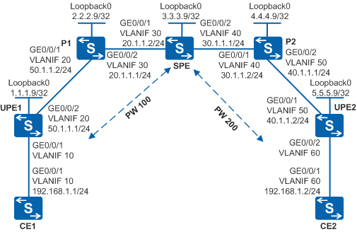
As shown in Figure 1, the carrier MPLS network provides L2VPN services for users. SPE has powerful functions, and UPE1 and UPE2 function as access devices and cannot directly establish a remote LDP session. UPE1 and UPE2 connect to many users with variable quantities. A VPN solution is required to provide secure VPN services and facilitate configuration and maintenance for new access users.

By default, LNP is enabled globally on the device. If a VLANIF interface is used as an AC-side interface for L2VPN, the configuration conflicts with LNP. In this case, run the lnp disable command in the system view to disable LNP.
The lnp disable command has no impact on services before the device restarts. After the device restarts, the device can only forward packets from the VLANs specified by the port default vlan command at Layer 2. The port default vlan 1 command is configured by default, so only packets of VLAN 1 can be forwarded at Layer 2.
Configuration Roadmap
Because SPE has powerful functions, and UPE1 and UPE2 cannot directly establish a remote LDP session, configure a multi-hop PW and PW switching on SPE. To facilitate maintenance, configure a dynamic multi-hop PW.
The configuration roadmap is as follows:
Configure an IGP protocol on the backbone network so that backbone network devices can communicate.
Configure basic MPLS functions and establish LSPs on the backbone network. Establish remote MPLS LDP peer relationships between UPE1 and SPE, and between UPE2 and SPE.
Create PW templates, and enable the control word function and LSP Ping.
Configure a dynamic PW on SPE.
Configure PW switching on SPE.
Procedure
- Configure VLANs that each interface belongs to and assign an IP address to each VLANIF interface according to Figure 1.
CE1 is used as an example.
# Configure CE1. The configuration on UPE1, UPE2, P1, P2, SPE, and CE2 is similar to the CE1, and is not mentioned here.
<HUAWEI> system-view
[HUAWEI] sysname CE1
[CE1] vlan batch 10
[CE1] interface vlanif 10
[CE1-Vlanif10] ip address 192.168.1.1 255.255.255.0
[CE1-Vlanif10] quit
[CE1] interface gigabitethernet 0/0/1
[CE1-GigabitEthernet0/0/1] port link-type trunk
[CE1-GigabitEthernet0/0/1] port trunk allow-pass vlan 10
[CE1-GigabitEthernet0/0/1] quit
- Configure an IGP protocol on the MPLS backbone network.
Configure an IGP protocol on the MPLS backbone network. This example uses OSPF.
When configuring OSPF, advertise 32-bit IP addresses of loopback interfaces on UPE1, SPE, and UPE2.
PE1 is used as an example.
# Configure UPE1. The configuration on UPE2, P1, P2, and SPE is similar to the UPE1, and is not mentioned here.
[UPE1]  interface loopback 0
[UPE1-LoopBack0] ip address 1.1.1.9 255.255.255.255
[UPE1-LoopBack0] quit
[UPE1] ospf 1
[UPE1-ospf-1] area 0
[UPE1-ospf-1-area-0.0.0.0] network 50.1.1.0 0.0.0.255
[UPE1-ospf-1-area-0.0.0.0] network 1.1.1.9 0.0.0.0
[UPE1-ospf-1-area-0.0.0.0] quit
[UPE1-ospf-1] quit
The configuration details of other devices are not mentioned here.
After the configuration, run the display ip routing-table command on UPEs, Ps and SPE. You can find that these devices have learnt the routes of each other.
UPEs can ping each other. The display on UPE1 is used as an example.
[UPE1] ping 40.1.1.2 PING 40.1.1.2: 56 data bytes, press CTRL_C to break Reply from 40.1.1.2: bytes=56 Sequence=1 ttl=252 time=160 ms Reply from 40.1.1.2: bytes=56 Sequence=2 ttl=252 time=120 ms Reply from 40.1.1.2: bytes=56 Sequence=3 ttl=252 time=150 ms Reply from 40.1.1.2: bytes=56 Sequence=4 ttl=252 time=150 ms Reply from 40.1.1.2: bytes=56 Sequence=5 ttl=252 time=160 ms --- 40.1.1.2 ping statistics --- 5 packet(s) transmitted 5 packet(s) received 0.00% packet loss round-trip min/avg/max = 120/148/160 ms - Enable MPLS, and set up LSP tunnels and remote LDP sessions.
Configure basic MPLS functions on the MPLS backbone network, and set up LSP tunnels and remote LDP sessions between UPE1 and SPE, and between SPE and UPE2.
# Configure UPE1.
[UPE1] mpls lsr-id 1.1.1.9
[UPE1] mpls
[UPE1-mpls] quit
[UPE1] mpls ldp
[UPE1-mpls-ldp] quit
[UPE1] interface vlanif 20
[UPE1-Vlanif20] mpls
[UPE1-Vlanif20] mpls ldp
[UPE1-Vlanif20] quit
[UPE1] mpls ldp remote-peer 3.3.3.9
[UPE1-mpls-ldp-remote-3.3.3.9] remote-ip 3.3.3.9
[UPE1-mpls-ldp-remote-3.3.3.9] quit
# Configure P1.
[P1] mpls lsr-id 2.2.2.9
[P1] mpls
[P1-mpls] quit
[P1] mpls ldp
[P1-mpls-ldp] quit
[P1] interface vlanif 20
[P1-Vlanif20] mpls
[P1-Vlanif20] mpls ldp
[P1-Vlanif20] quit
[P1] interface vlanif 30
[P1-Vlanif30] mpls
[P1-Vlanif30] mpls ldp
[P1-Vlanif30] quit
# Configure SPE.
[SPE] mpls lsr-id 3.3.3.9
[SPE] mpls
[SPE-mpls] quit
[SPE] mpls ldp
[SPE-mpls-ldp] quit
[SPE] interface vlanif 30
[SPE-Vlanif30] mpls
[SPE-Vlanif30] mpls ldp
[SPE-Vlanif30] quit
[SPE] interface vlanif 40
[SPE-Vlanif40] mpls
[SPE-Vlanif40] mpls ldp
[SPE-Vlanif40] quit
[SPE] mpls ldp remote-peer 1.1.1.9
[SPE-mpls-ldp-remote-1.1.1.9] remote-ip 1.1.1.9
[SPE-mpls-ldp-remote-1.1.1.9] quit
[SPE] mpls ldp remote-peer 5.5.5.9
[SPE-mpls-ldp-remote-5.5.5.9] remote-ip 5.5.5.9
[SPE-mpls-ldp-remote-5.5.5.9] quit
# Configure P2.
[P2] mpls lsr-id 4.4.4.9
[P2] mpls
[P2-mpls] quit
[P2] mpls ldp
[P2-mpls-ldp] quit
[P2] interface vlanif 40
[P2-Vlanif40] mpls
[P2-Vlanif40] mpls ldp
[P2-Vlanif40] quit
[P2] interface vlanif 50
[P2-Vlanif50] mpls
[P2-Vlanif50] mpls ldp
[P2-Vlanif50] quit
# Configure UPE2.
[UPE2] mpls lsr-id 5.5.5.9
[UPE2] mpls
[UPE2-mpls] quit
[UPE2] mpls ldp
[UPE2-mpls-ldp] quit
[UPE2] interface vlanif 50
[UPE2-Vlanif50] mpls
[UPE2-Vlanif50] mpls ldp
[UPE2-Vlanif50] quit
[UPE2] mpls ldp remote-peer 3.3.3.9
[UPE2-mpls-ldp-remote-3.3.3.9] remote-ip 3.3.3.9
[UPE2-mpls-ldp-remote-3.3.3.9] quit
After the configuration is complete, run the display mpls ldp session command on UPEs, Ps, or SPE. You can see that the Status field is Operational. Run the display mpls ldp peer command. You can view the LDP peer status. Run the display mpls lsp command to view the LSP status. The display on SPE is used as an example.
[SPE] display mpls ldp session

 LDP Session(s) in Public Network
 Codes: LAM(Label Advertisement Mode), SsnAge Unit(DDDD:HH:MM)
 A '*' before a session means the session is being deleted.
 ------------------------------------------------------------------------------
 PeerID             Status      LAM  SsnRole  SsnAge      KASent/Rcv
 ------------------------------------------------------------------------------
 1.1.1.9:0          Operational DU   Active   0000:00:14  57/57
 2.2.2.9:0          Operational DU   Active   0000:00:14  56/56
 4.4.4.9:0          Operational DU   Passive  0000:00:05  22/22
 5.5.5.9:0          Operational DU   Passive  0000:00:12  52/52
 ------------------------------------------------------------------------------
 TOTAL: 4 session(s) Found.
[SPE] display mpls ldp peer

LDP Peer Information in Public network
 A '*' before a peer means the peer is being deleted.
 ------------------------------------------------------------------------------
 PeerID                TransportAddress   DiscoverySource
 ------------------------------------------------------------------------------
 1.1.1.9:0             1.1.1.9            Remote Peer : 1.1.1.9
 2.2.2.9:0             2.2.2.9            Vlanif30
 4.4.4.9:0             4.4.4.9            Vlanif40
 5.5.5.9:0             5.5.5.9            Remote Peer : 5.5.5.9
 ------------------------------------------------------------------------------
 TOTAL: 4 Peer(s) Found.
[SPE] display mpls lsp Flag after Out IF: (I) - LSP Is Only Iterated by RLFA ------------------------------------------------------------------------------- LSP Information: LDP LSP ------------------------------------------------------------------------------- FEC In/Out Label In/Out IF Vrf Name 1.1.1.9/32 NULL/1024 -/Vlanif30 1.1.1.9/32 1024/1024 -/Vlanif30 2.2.2.9/32 NULL/3 -/Vlanif30 2.2.2.9/32 1025/3 -/Vlanif30 3.3.3.9/32 3/NULL -/- 4.4.4.9/32 NULL/3 -/Vlanif40 4.4.4.9/32 1027/3 -/Vlanif40 5.5.5.9/32 NULL/1027 -/Vlanif40 5.5.5.9/32 1026/1027 -/Vlanif40 - Create and configure PW templates.
Create PW templates on UPEs, and enable the control word function and LSP Ping.
# Configure UPE1.
[UPE1] mpls l2vpn
[UPE1-l2vpn] quit
[UPE1] pw-template pwt
[UPE1-pw-template-pwt] peer-address 3.3.3.9
[UPE1-pw-template-pwt] control-word
[UPE1-pw-template-pwt] quit
# Configure UPE2.
[UPE2] mpls l2vpn
[UPE2-l2vpn] quit
[UPE2] pw-template pwt
[UPE2-pw-template-pwt] peer-address 3.3.3.9
[UPE2-pw-template-pwt] control-word
[UPE2-pw-template-pwt] quit
You can also configure a dynamic PW without using the PW template. If the PW template is not used, PW connectivity cannot be verified and path information of the PW cannot be collected. That is, you cannot run the ping vc or tracert vc command.
- Create VCs.
Enable MPLS L2VPN on UPE1, UPE2, and SPE.
Configure dynamic PWs on UPEs, and configure PW switching on SPE.
# Configure UPE1.In this example, a VLANIF interface is used as the AC-side interface, so you need to run the lnp disable command in the system view before performing the following steps. If you cannot disable LNP on the live network, do not use a VLANIF interface as the AC-side interface.
[UPE1] interface vlanif 10
[UPE1-Vlanif10] mpls l2vc pw-template pwt 100
[UPE1-Vlanif10] quit
# Configure SPE.
[SPE] mpls l2vpn
[SPE-l2vpn] quit
[SPE] mpls switch-l2vc 1.1.1.9 100 between 5.5.5.9 200 encapsulation vlan
# Configure UPE2.In this example, a VLANIF interface is used as the AC-side interface, so you need to run the lnp disable command in the system view before performing the following steps. If you cannot disable LNP on the live network, do not use a VLANIF interface as the AC-side interface.
[UPE2] interface vlanif 60
[UPE2-Vlanif60] mpls l2vc pw-template pwt 200
[UPE2-Vlanif60] quit
- Verify the configuration.
View the PWE3 connection.
View the L2VPN connection on the UPE and SPE. You can see that an L2VC is set up and the VC status is Up.
The display on UPE1 is used as an example.
[UPE1] display mpls l2vc interface vlanif 10
 *client interface       : Vlanif10 is up
  Administrator PW       : no
  session state          : up
  AC status              : up
  Ignore AC state        : disable
  VC state               : up
  Label state            : 0
  Token state            : 0
  VC ID                  : 100
  VC type                : VLAN
  destination            : 3.3.3.9
  local group ID         : 0            remote group ID      : 0
  local VC label         : 8195        remote VC label      : 8196
  local AC OAM State     : up
  local PSN OAM State    : up
  local forwarding state : forwarding
  local status code      : 0x0
  remote AC OAM state    : up
  remote PSN OAM state   : up
  remote forwarding state: forwarding
  remote status code     : 0x0
  ignore standby state   : no
  BFD for PW             : unavailable
  VCCV State             : up
  manual fault           : not set
  active state           : active
  forwarding entry       : exist
  link state             : up
  local VC MTU           : 1500         remote VC MTU        : 1500
  local VCCV             : cw alert lsp-ping bfd
  remote VCCV            : cw alert lsp-ping bfd
  local control word     : enable       remote control word  : enable
  tunnel policy name     : --
  PW template name       : pwt
  primary or secondary   : primary
  load balance type      : flow
  Access-port            : false
  Switchover Flag        : false
  VC tunnel/token info   : 1 tunnels/tokens
    NO.0  TNL type       : lsp   , TNL ID : 0x27
    Backup TNL type      : lsp   , TNL ID : 0x0
  create time            : 0 days, 0 hours, 15 minutes, 3 seconds
  up time                : 0 days, 0 hours, 3 minutes, 15 seconds
  last change time       : 0 days, 0 hours, 3 minutes, 15 seconds
  VC last up time        : 2011/01/27 12:31:31
  VC total up time       : 0 days, 2 hours, 12 minutes, 51 seconds
  CKey                   : 16
  NKey                   : 15
  PW redundancy mode     : frr
  AdminPw interface      : --
  AdminPw link state     : --
  Diffserv Mode          : uniform
  Service Class          : --
  Color                  : --
  DomainId               : --
  Domain Name            : --
Check the L2VC status on SPE.
[SPE] display mpls switch-l2vc
Total Switch VC : 1, 1 up, 0 down

*Switch-l2vc type             : LDP<---->LDP
 Peer IP Address              : 1.1.1.9, 5.5.5.9
 VC ID                        : 100, 200
 VC Type                      : VLAN
 VC State                     : up
 VC StatusCode                |PSN |OAM | FW |    |PSN |OAM | FW |
                   -Local VC :| UP | UP | UP |    | UP | UP | UP |
                   -Remote VC:| UP | UP | UP |    | UP | UP | UP |
 Session State                : up, up
 Local/Remote Label           : 8195/8195, 8196/8195
 InLabel Status               : 0 , 0
 Local/Remote MTU             : 1500/1500, 1500/1500
 Local/Remote Control Word    : Enable/Enable, Enable/Enable
 Local/Remote VCCV Capability : cw alert ttl lsp-ping bfd /cw alert ttl lsp-ping bfd , cw alert ttl lsp-ping bfd /cw alert ttl lsp-ping bfd
 Switch-l2vc tunnel info      :
                                1 tunnels for peer 1.1.1.9
                                NO.0  TNL Type : lsp   , TNL ID : 0x48002004
                                1 tunnels for peer 5.5.5.9
                                NO.0  TNL Type : lsp   , TNL ID : 0x48002000
 CKey                         : 4, 2
 NKey                         : 3, 1
 Tunnel policy                : --, --
 Control-Word transparent     : NO
 Create time                  : 0 days, 0 hours, 13 minutes, 1 seconds
 UP time                      : 0 days, 0 hours, 3 minutes, 58 seconds
 Last change time             : 0 days, 0 hours, 3 minutes, 58 seconds
 VC last up time              : 2010/01/27 12:46:59
 VC total up time             : 0 days, 0 hours, 0 minutes, 24 seconds
Detect connectivity of the PW.
Run the ping vc command on the UPE. You can see that connectivity of the PW is normal. The display on UPE1 is used as an example.
[UPE1] ping vc vlan 100 control-word remote 5.5.5.9 200
    Reply from 5.5.5.9: bytes=100 Sequence=1 time = 740 ms
    Reply from 5.5.5.9: bytes=100 Sequence=2 time = 90 ms
    Reply from 5.5.5.9: bytes=100 Sequence=3 time = 160 ms
    Reply from 5.5.5.9: bytes=100 Sequence=4 time = 130 ms
    Reply from 5.5.5.9: bytes=100 Sequence=5 time = 160 ms

  --- FEC: FEC 128 PSEUDOWIRE (NEW). Type = vlan, ID = 100 ping statistics ---
    5 packet(s) transmitted
    5 packet(s) received
    0.00% packet loss
    round-trip min/avg/max = 90/256/740 ms
Check connectivity between CEs and information about the path between CEs.
CE1 and CE2 can ping each other.
[CE1] ping 192.168.1.2
  PING 192.168.1.2: 56  data bytes, press CTRL_C to break
    Reply from 192.168.1.2: bytes=56 Sequence=1 ttl=255 time=180 ms
    Reply from 192.168.1.2: bytes=56 Sequence=2 ttl=255 time=120 ms
    Reply from 192.168.1.2: bytes=56 Sequence=3 ttl=255 time=160 ms
    Reply from 192.168.1.2: bytes=56 Sequence=4 ttl=255 time=160 ms
    Reply from 192.168.1.2: bytes=56 Sequence=5 ttl=255 time=130 ms

  --- 192.168.1.2 ping statistics ---
    5 packet(s) transmitted
    5 packet(s) received
    0.00% packet loss
    round-trip min/avg/max = 120/150/180 ms
On CE1, perform tracert.
[CE1] tracert 192.168.1.2
traceroute to  192.168.1.2(192.168.1.2), max hops: 30 ,packet length: 40,press CTRL_C to break
1 192.168.1.2 5 ms  5 ms  19 ms
Configuration Files
CE1 configuration file
#
sysname CE1
#
vlan batch 10
#
interface Vlanif10
 ip address 192.168.1.1 255.255.255.0
#
interface GigabitEthernet0/0/1
 port link-type trunk
 port trunk allow-pass vlan 10
#
return
UPE1 configuration file

The lnp disable command has no impact on services before the device restarts. After the device restarts, the device can only forward packets from the VLANs specified by the port default vlan command at Layer 2. The port default vlan 1 command is configured by default, so only packets of VLAN 1 can be forwarded at Layer 2.
#
sysname UPE1
#
vlan batch 10 20
#
lnp disable #mpls lsr-id 1.1.1.9
mpls
#
mpls l2vpn
#
pw-template pwt
 peer-address 3.3.3.9
 control-word
#
mpls ldp
#
mpls ldp remote-peer 3.3.3.9
 remote-ip 3.3.3.9
#
interface Vlanif10
 mpls l2vc pw-template pwt 100
#
interface Vlanif20
 ip address 50.1.1.1 255.255.255.0
 mpls
 mpls ldp
#
interface GigabitEthernet0/0/1
 port link-type trunk
 port trunk allow-pass vlan 10
#
interface GigabitEthernet0/0/2
 port link-type trunk
 port trunk allow-pass vlan 20
#
interface LoopBack0
 ip address 1.1.1.9 255.255.255.255
#
ospf 1
 area 0.0.0.0
  network 1.1.1.9 0.0.0.0
  network 50.1.1.0 0.0.0.255
#
return
P1 configuration file
#
sysname P1
#
vlan batch 20 30
#
mpls lsr-id 2.2.2.9
mpls
#
mpls ldp
#
interface Vlanif20
 ip address 50.1.1.2 255.255.255.0
 mpls
 mpls ldp
#
interface Vlanif30
 ip address 20.1.1.1 255.255.255.0
 mpls
 mpls ldp
#
interface GigabitEthernet0/0/1
 port link-type trunk
 port trunk allow-pass vlan 20
#
interface GigabitEthernet0/0/2
 port link-type trunk
 port trunk allow-pass vlan 30
#
interface LoopBack0
 ip address 2.2.2.9 255.255.255.255
#
ospf 1
 area 0.0.0.0
  network 2.2.2.9 0.0.0.0
  network 20.1.1.0 0.0.0.255
  network 50.1.1.0 0.0.0.255
#
return
SPE configuration file
#
sysname SPE
#
vlan batch 30 40
#
mpls lsr-id 3.3.3.9
mpls
#
mpls l2vpn
#
mpls switch-l2vc 1.1.1.9 100 between 5.5.5.9 200 encapsulation vlan
#
mpls ldp
#
mpls ldp remote-peer 1.1.1.9
 remote-ip 1.1.1.9
#
mpls ldp remote-peer 5.5.5.9
 remote-ip 5.5.5.9
#
interface Vlanif30
 ip address 20.1.1.2 255.255.255.0
 mpls
 mpls ldp
#
interface Vlanif40
 ip address 30.1.1.1 255.255.255.0
 mpls
 mpls ldp
#
interface GigabitEthernet0/0/1
 port link-type trunk
 port trunk allow-pass vlan 30
#
interface GigabitEthernet0/0/2
 port link-type trunk
 port trunk allow-pass vlan 40
#
interface LoopBack0
 ip address 3.3.3.9 255.255.255.255
#
ospf 1
 area 0.0.0.0
  network 3.3.3.9 0.0.0.0
  network 20.1.1.0 0.0.0.255
  network 30.1.1.0 0.0.0.255
#
return
P2 configuration file
#
sysname P2
#
vlan batch 40 50
#
mpls lsr-id 4.4.4.9
mpls
#
mpls ldp
#
interface Vlanif40
 ip address 30.1.1.2 255.255.255.0
 mpls
 mpls ldp
#
interface Vlanif50
 ip address 40.1.1.1 255.255.255.0
 mpls
 mpls ldp
#
interface GigabitEthernet0/0/1
 port link-type trunk
 port trunk allow-pass vlan 40
#
interface GigabitEthernet0/0/2
 port link-type trunk
 port trunk allow-pass vlan 50
#
interface LoopBack0
 ip address 4.4.4.9 255.255.255.255
#
ospf 1
 area 0.0.0.0
  network 4.4.4.9 0.0.0.0
  network 30.1.1.0 0.0.0.255
  network 40.1.1.0 0.0.0.255
#
return
UPE2 configuration file
The lnp disable command has no impact on services before the device restarts. After the device restarts, the device can only forward packets from the VLANs specified by the port default vlan command at Layer 2. The port default vlan 1 command is configured by default, so only packets of VLAN 1 can be forwarded at Layer 2.
#
sysname UPE2
#
vlan batch 50 60
#
lnp disable #mpls lsr-id 5.5.5.9
mpls
#
mpls l2vpn
#
pw-template pwt
 peer-address 3.3.3.9
 control-word
#
mpls ldp
#
mpls ldp remote-peer 3.3.3.9
 remote-ip 3.3.3.9
#
interface Vlanif50
 ip address 40.1.1.2 255.255.255.0
 mpls
 mpls ldp
#
interface Vlanif60
 mpls l2vc pw-template pwt 200
#
interface GigabitEthernet0/0/1
 port link-type trunk
 port trunk allow-pass vlan 50
#
interface GigabitEthernet0/0/2
 port link-type trunk
 port trunk allow-pass vlan 60
#
interface LoopBack0
 ip address 5.5.5.9 255.255.255.255
#
ospf 1
 area 0.0.0.0
  network 5.5.5.9 0.0.0.0
  network 40.1.1.0 0.0.0.255
#
return
CE2 configuration file
#
sysname CE2
#
vlan batch 60
#
interface Vlanif60
 ip address 192.168.1.2 255.255.255.0
#
interface GigabitEthernet0/0/1
 port link-type trunk
 port trunk allow-pass vlan 60
#
return